Pressure sensor connectivity: HART, Modbus, or IO-Link paths
A pressure transmitter can be reading perfectly while still creating a miserable shift for the people responsible for it.
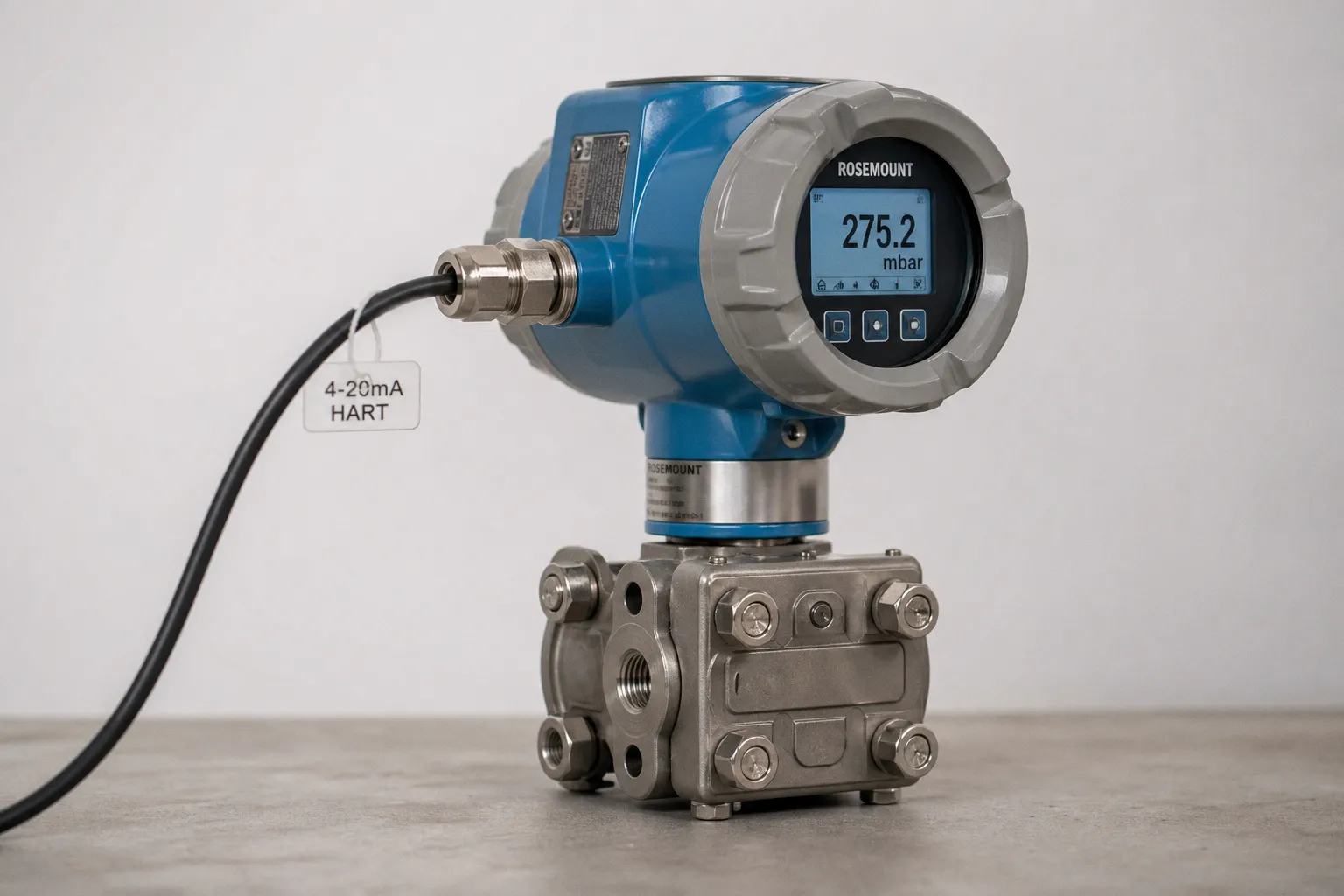
The value reaches the controller, the process stays inside its limits, and yet when a pump begins cycling strangely or a filter starts loading up, somebody has to walk to the instrument, open a cabinet, connect a handheld tool, and work out whether the problem is pressure, wiring, scaling, configuration, or the sensor itself.
Compare car rental deals in United Kingdom
See available offersPartner link — DiscoverCars comparisonThat is the practical choice behind industrial pressure sensor communication protocol options. HART, Modbus, and IO-Link are often compared as though they were three interchangeable labels on a purchasing sheet. On the ground, they solve different connection problems. One preserves an analog control loop while adding digital visibility. One puts a device on a shared serial or Ethernet network. One gives a sensor a short, intelligent link to a nearby master. Choosing well starts by seeing those architectures clearly.
Three paths, three different jobs
The first useful correction is simple: HART, Modbus, and IO-Link do not occupy the same place in an automation stack.
HART is built around the familiar 4–20 mA loop. The primary pressure measurement continues to travel as analog current, while a digital signal rides on the same pair of wires. This is especially valuable in plants where analog input cards, loop-powered transmitters, established commissioning routines, and long service histories are not inconveniences but real assets.
Modbus is an application-layer messaging protocol. It can run over serial media such as EIA/TIA-232, EIA/TIA-422, and EIA/TIA-485-A, or over Ethernet using Modbus/TCP. A pressure device becomes a network participant from which a PLC, HMI, gateway, or supervisory system reads defined data points. This changes the conversation from “what current is on this loop?” to “which register holds pressure, status, temperature, or a fault code?”
IO-Link is neither an analog overlay nor a fieldbus. It is a wired, point-to-point interface between one IO-Link device and one port on an IO-Link master. The master then connects upward into the wider automation network. That distinction matters because it tells us where IO-Link feels most natural: close to machines, manifolds, skids, packaging equipment, test rigs, and other places where sensor replacement, parameter consistency, and local diagnostics have a direct effect on operator fatigue.
| Question | HART | Modbus | IO-Link |
|---|---|---|---|
| Basic architecture | Digital signal over a 4–20 mA loop | Client/server messaging over serial or TCP/IP | Point-to-point device-to-master link |
| Primary process value | Analog current remains available | Read as device data/registers | Sent as process data through the master |
| Best natural fit | Modernizing or retaining analog instrumentation | Networked PLC, SCADA, and remote monitoring architectures | Machine-level sensors with fast replacement and parameter needs |
| Diagnostic path | Digital information on existing loop wiring | Device-specific registers or data objects | Bidirectional diagnostics and parameters via master |
| Wiring boundary | Existing instrument loop | Depends on serial or Ethernet physical layer | Maximum 20 m from master port to device |
| Common misunderstanding | “Digital HART replaces 4–20 mA” | “All Modbus devices expose data the same way” | “IO-Link is a fieldbus” |
If you are specifying a new booster station cabinet, for example, this is not a philosophical distinction. It determines the I/O cards in the cabinet, the commissioning screen the technician sees, the spare sensor kept in stores, and the route a fault takes from the sensing element to the person who needs to act on it.
The best protocol is not the one with the longest feature list; it is the one that leaves the fewest unanswered questions when the pressure reading stops making sense at 2 a.m.
HART: keeping the loop while opening a diagnostic door
HART remains compelling because it respects the physical reality of installed plants. Many water, process, and utility systems are built around 4–20 mA instruments. The current loop is understood by electricians, accepted by legacy control systems, and often already present in cable trays that are not about to be reopened just because a digital alternative exists.
In a HART pressure transmitter, the analog and digital channels work simultaneously. The 4–20 mA signal continues to represent the primary measured value, while HART communication uses Bell 202 frequency-shift keying superimposed on that same loop. The digital channel operates at 1,200 bit/s, with typically two to three primary-variable updates per second.
That rate sounds modest beside Ethernet numbers, but it answers a different need. HART is not trying to become a high-speed machine bus. It gives maintenance and engineering teams access to configuration, device status, diagnostics, and potentially supplementary variables without abandoning the analog signal that the control strategy already trusts.
This makes HART particularly practical in several situations:
- An existing analog pressure loop needs better serviceability. If the transmitter is already wired to an analog input card, a HART-capable host, multiplexer, or handheld communicator can expose information without a wholesale I/O redesign.
- The control loop must retain a direct analog fallback. The PLC can continue consuming 4–20 mA as its primary input while technicians use the digital layer for setup and health information.
- A plant has long cable routes and field instruments distributed across a large footprint. The design must still be checked against the specific transmitter, loop supply, load resistance, cable, and host equipment, but the architecture is familiar to instrumentation teams.
- The operational problem is configuration drift, not bandwidth. A pressure transmitter that has been ranged incorrectly after replacement can cause far more trouble than a slow diagnostic exchange.
There is a design detail we should not skip: HART capability is not automatically useful merely because “HART” appears on the transmitter datasheet. The host side must be able to communicate with it. That may mean HART-enabled analog input cards, a compatible I/O system, a multiplexer, or a maintenance tool. It also means confirming what the specific transmitter exposes. HART revisions, supported commands, device descriptions, and diagnostic depth vary by device and host integration.
If-then logic helps here. If your PLC only needs one pressure value for control and the physical loop is already installed, then HART may add a valuable maintenance layer with minimal disturbance. If you expect the system to collect multiple values continuously from many devices into a central monitoring platform, then HART can still be part of the answer, but you should first ask whether the host architecture makes that data accessible without creating a tangle of converters and exceptions.
The most humane aspect of HART is that it can improve visibility without demanding that the operator relearn the entire plant. The gauge, the loop, and the control logic still behave in recognizable ways. The digital information arrives as an extra handrail rather than a new staircase.
Modbus: a network conversation, not a universal plug shape
Modbus appears everywhere because it is straightforward to implement and widely supported across PLCs, gateways, drives, meters, remote I/O, and monitoring platforms. But “the pressure sensor speaks Modbus” is the beginning of the design conversation, not the end.
Modbus is an application-layer protocol based on client/server communication. It can be carried over serial networks or over TCP/IP Ethernet. In the Ethernet form, Modbus/TCP application data uses registered TCP port 502. The protocol gives the controller or software client a way to request data from a server device. For a pressure transmitter, that may include the measured pressure, status flags, alarms, temperature, totalized values, or configuration values—but the exact content is always device-specific.
That last point is where many commissioning hours disappear. A register map is not a universal language in the way people often hope. One transmitter may place pressure in two input registers as a floating-point value. Another may use holding registers, a scaled integer, a different byte order, or a separate register for engineering units. A device may offer rich diagnostics; another may expose little beyond the measurement and a generic status word.
Before selecting Modbus for a pressure application, we should settle five practical questions:
1. Which physical network are we actually building? Modbus RTU over RS-485 and Modbus/TCP over Ethernet have very different cable, topology, addressing, grounding, switch, and troubleshooting realities. “Modbus” alone does not answer them.
2. Who is the client, and how often will it poll? A PLC, edge gateway, SCADA server, or industrial PC may all read the same sensor differently. Polling time has to fit the actual process need and the number of devices sharing the path; there is no fixed Modbus update rate that applies everywhere.
3. What is the register map for this exact transmitter model? Confirm data type, register addressing convention, scaling, byte order, status registers, writable parameters, and fault behavior from the manufacturer documentation before controls code is written.
4. What happens when communication fails? The control design needs a defined response. Does the PLC hold the last good value, declare a fault after a timeout, switch to a backup measurement, or stop a pump? That decision belongs in the process risk discussion, not as an afterthought in the HMI.
5. Where does the network cross a security boundary? Standard Modbus/TCP on port 502 does not automatically provide encryption, certificate authentication, or message integrity protection. The separate Modbus Security profile uses TLS and X.509v3 certificates, with port 802. Whether that profile is available and suitable depends on the actual devices and network design.
Modbus earns its place when the pressure reading needs to travel beyond the local cabinet as structured digital information. Consider a distributed water treatment system with pump stations, pressure zones, remote telemetry, and a central operations room. If the architecture already uses Ethernet or serial remote I/O, Modbus can be a sensible path from instrumentation into monitoring and control—provided the register documentation, communications handling, and cybersecurity design are treated as part of the equipment scope.
This is also where the difference between analog vs digital sensor signals becomes operationally visible. With analog, a broken loop or out-of-range current can be managed through well-known conventions, but the information content is limited. With Modbus, one cable can carry a richer set of values and states, but the system now depends on correct network behavior, polling logic, and data interpretation. Neither is inherently more reliable in every setting. They distribute responsibility differently.
Modbus gives you more data only if somebody has designed the path from that data to a decision.
IO-Link: the short connection that makes replacement less painful
IO-Link is often the cleanest answer for pressure sensing inside a machine envelope. It is standardized in IEC 61131-9 and provides bidirectional communication between a device and an IO-Link master. The device sends process data, while the master can read diagnostics and write parameters. The master then serves as the bridge to the higher-level fieldbus or Ethernet architecture.
It is worth saying plainly: IO-Link is not a fieldbus. It is a device-to-master interface. That is not a limitation; it is its strength. The interface is designed for the last segment of connectivity, where a pressure sensor is mounted on a pneumatic manifold, hydraulic power unit, filtration skid, or compact pump package and where somebody will eventually need to replace it with gloves on, limited visibility, and a production schedule waiting in the background.
IO-Link defines three communication rates:
- COM1: 4.8 kbit/s
- COM2: 38.4 kbit/s
- COM3: 230.4 kbit/s
The relevant distance is equally specific: the connection between an IO-Link master port and one device is limited to 20 m. This is not a 20 m limit for the whole plant network. A machine may have many masters connected onward through industrial Ethernet, with each field device using its own short cable run to the nearest master.
For devices drawing less than 200 mA, the IO-Link design guidance allows a 0.35 mm² cable up to 20 m on that master-to-device segment without a separate voltage-drop calculation. That is helpful as a design reference, not permission to stop thinking. Actual current draw, cable construction, connector choice, environmental exposure, and the master’s power arrangement still belong in the selection review.
The practical benefit that operators notice is not the protocol speed. It is repeatability.
A conventional pressure switch or analog sensor replacement can involve checking the range, setting a switch point, confirming units, adjusting damping, and hoping the new device was configured like the old one. With IO-Link, the device description file—the IODD—supports setup, operation, and maintenance, while the master can manage parameters and diagnostics. If the system is configured properly, a replacement sensor can receive the approved settings rather than relying on memory, handwritten cabinet notes, or a hurried technician navigating a tiny local display.
That reduces operator fatigue in a very ordinary but consequential way. Instead of being asked to diagnose whether a pump is behaving oddly because “the new sensor might be set differently,” the team starts from a more stable baseline.
IO-Link pressure sensor benefits become especially clear in these real-world contexts:
- Skid builders need repeatable machine builds. A standardized master, cable family, sensor model, and parameter set can move from one skid to the next with less custom wiring and fewer manual setup variations.
- Maintenance teams replace sensors frequently or across many similar machines. Parameter handling can reduce the number of steps required to return equipment to a known working state.
- The machine needs more than a single process value. A pressure reading, device status, and condition information can travel through the same point-to-point connection.
- The sensor is close enough to a master. The 20 m master-to-device limit must fit the physical layout. If the sensor is on a distant tank or across a sprawling process area, putting a master near it may be possible, but it changes the cabinet and network design.
There is also a tactile dimension that gets lost in architecture diagrams. A well-designed IO-Link installation still needs robust connectors, cable routing that survives washdown or vibration, readable port identification, and an HMI that makes a device fault distinguishable from a process fault. Digital connectivity does not eliminate physical work. It should make physical work more legible.
Choosing the path from the cabinet outward
Protocol selection should begin at the pressure point and move outward through the actual system, rather than beginning with a preferred technology and forcing the hardware to comply.
Start with the pressure device itself. Not every transmitter is offered in every interface, and even devices sharing a protocol label may differ substantially in diagnostic depth, pressure range handling, accuracy behavior, approvals, connection type, display options, and parameter availability. A pressure sensor on a sanitary skid, a high-cycle hydraulic fixture, and an inlet header at a water pumping station may all measure pressure, but they do not create the same connectivity problem.
Then look at the immediate hardware around it:
- Available control I/O: Do you have analog input channels with HART capability, serial ports, Ethernet capacity, or unused IO-Link master ports?
- Cabinet geography: Is the device within 20 m of an IO-Link master? Is a local field junction box realistic? Are existing analog pairs already installed?
- Control behavior: Does the loop need a continuously available analog primary value, or is a polled digital value appropriate for the process response required?
- Service model: Will an instrument technician use a handheld tool, will a maintenance electrician replace a sensor at the machine, or will a remote operations team need central diagnostics?
- Data destination: Is the value only feeding a local PLC function, or is it also entering a historian, dashboard, digital twin, alarm management layer, or remote monitoring system?
- Failure and security design: How is signal loss detected? Who can change parameters? Which network segment is exposed beyond the machine or site boundary?
The answer often becomes clearer when we state the if-then conditions without ceremony.
If you are retrofitting a legacy pump control cabinet where the process is already designed around 4–20 mA, then HART is usually the least disruptive route to stronger diagnostics and configuration access. You retain a familiar primary signal and add a digital service channel where the host hardware supports it.
If you are connecting pressure transmitters into an established PLC and SCADA network, especially across distributed assets where structured device data belongs in a central system, then Modbus may be the natural fit. But budget time for register-map verification, communications testing, failure handling, and network security—not simply for landing wires.
If you are building or standardizing a compact machine, skid, or modular control package where sensor replacement and parameter consistency matter every week, then IO-Link can make the whole interaction cleaner. Place the master deliberately, respect the 20 m device segment, and treat the IODD and parameter set as part of the machine’s maintained design record.
The hidden cost is usually at commissioning
The purchase price difference between interface variants can attract a lot of attention. In practice, the expensive part is more often the mismatch discovered after installation: an analog card that does not expose HART data, a Modbus device whose floating-point order is not what the PLC programmer assumed, an IO-Link sensor mounted 28 m from the nearest master, or a dashboard that receives a pressure value but cannot tell whether it is current, stale, substituted, or invalid.
We can avoid much of that friction by making connectivity part of the pressure-sensor specification itself. The specification should name the exact sensor model or approved family, the controller or master interface, the required process values, the diagnostics that must be visible, the expected update behavior, the cable route, and the response to communications loss. It should also state who owns parameter backups and device replacement procedures.
This is particularly important for systems that combine local control with remote oversight. A digital twin or central monitoring platform is only as useful as the signals arriving in it. If the system cannot distinguish low suction pressure from a disconnected transmitter, the screen may look sophisticated while leaving the person on the ground with the same old uncertainty.
HART, Modbus, and IO-Link are all capable industrial sensor connectivity paths. They simply ask different things of the hardware, the cabinet, the network, and the people who maintain them. HART preserves the analog loop and adds a window into the instrument. Modbus extends device information into a networked control and monitoring conversation. IO-Link organizes the last few metres around the sensor so that configuration and diagnostics travel with the device.
The most durable design is the one that respects the worker standing in front of the cabinet: a pressure value they can trust, a fault they can identify, and a replacement process that does not turn a small sensor into a long interruption of their day.