Remote pump monitoring integration: pre-deployment site checklist
Most remote pump monitoring projects do not fail because someone picked the wrong cellular gateway. They fail because the team treats the gateway as the project.
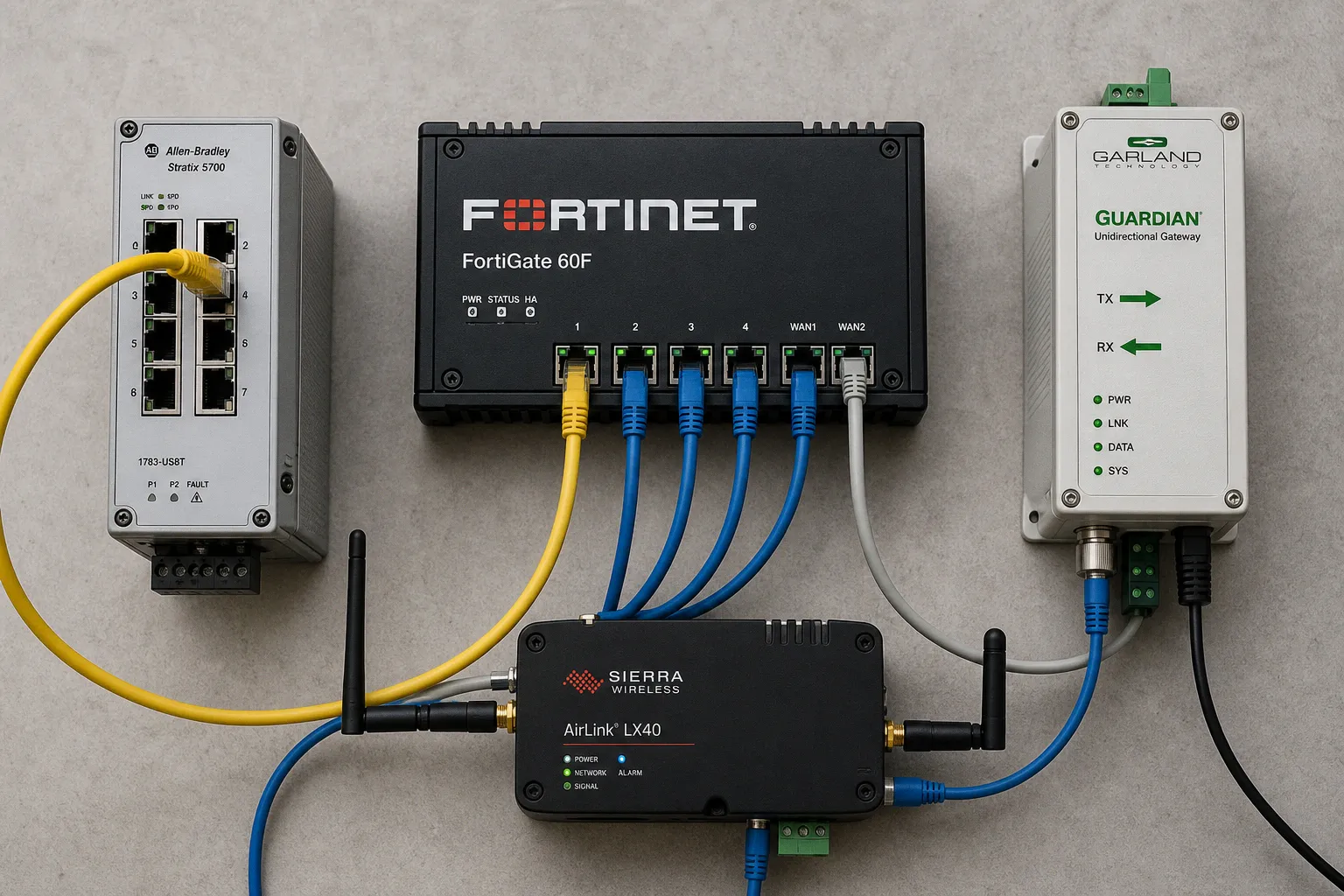
A controller gets mounted in a cabinet, a dashboard appears, a few trend lines move, and someone announces “visibility.” Then the first suction-pressure fault arrives at 2 a.m., nobody knows whether the point is scaled correctly, the VFD ignores the command they thought it would receive, and the cellular router dies three hours into a utility outage. That is not Industrial IoT. That is expensive noise with a login screen.
I use this remote pump monitoring system integration checklist before hardware ships, before a panel schedule gets locked, and certainly before anyone opens a firewall rule “temporarily.” The point is not to produce more documentation bloat. The point is to expose the decisions that otherwise get buried inside an over-engineered panel, an unlabeled PLC program, or an installer’s assumptions.
A remote monitoring system is not “connected” when it has a dashboard. It is connected when every signal, command, failure mode, and network path has an owner and a defined response.
Start with the pump site, not the cloud platform
The usual sales deck begins with architecture diagrams: sensors, edge gateway, cloud, dashboard. Nice arrows. Zero hydraulic context. That order is backwards.
A pump station has process behavior before it has telemetry. The monitoring design must begin with the pump train, the control panel, the motor starter or VFD, the pressure boundary, and the operator’s actual decisions. If the system cannot distinguish a dry-run indication from a blocked discharge, it does not need another dashboard widget. It needs a proper point list.
For pump automation telemetry planning, I map four things at the same time:
1. The physical asset chain. Identify each pump, motor, VFD or starter, pressure transmitter, flow meter, level device, isolation valve, check valve, local HOA selector, emergency-stop circuit, generator interface, and panel power supply. “Pump Station 4” is not an asset map. It is a label people use when they have not done the work.
2. The signal chain. For every point, document where the value originates, how it travels, where it is scaled, where it is displayed, and where it becomes an alarm. A pressure transmitter may feed a VFD analog input, a PLC analog card, both through an isolator, or neither if someone installed it only for a local gauge. Those are radically different designs.
3. The decision chain. State what an operator can do with the information. A low-discharge-pressure alarm might trigger a callout, block a pump start, switch duty pumps, or simply show red on a screen that nobody watches. Do not collapse those outcomes into one vague word: “alarm.”
4. The authority chain. Name who owns the setpoints, alarm changes, firmware, user accounts, SIM cards, and remote-access rules. If the answer is “the integrator,” ask which person, under which contract, and after that contract ends. Silence here becomes operational friction later.
I want the team to classify every point in plain language before it appears in a tag database:
| Point class | What it does | Typical pump-station example | Common bad pattern |
|---|---|---|---|
| Status | Reports a discrete state | Pump running, VFD fault, panel door open | Treating “run command present” as proof that the motor runs |
| Measurement | Reports a process or electrical value | Discharge pressure, wet-well level, motor current | Recording an engineering value without documenting scaling |
| Alarm | Signals an abnormal condition requiring a response | Low inlet pressure, dry-run warning, communications loss | Turning every abnormal value into the same priority alarm |
| Command | Requests a controlled action | Start, stop, duty selection, reset request | Giving a dashboard command authority without interlock review |
| Setpoint | Changes a control target | Pressure PID target, alternation interval | Letting remote users change it because the field exists in the platform |
The counterpoint: do not call all data “telemetry.” A hardwired motor fault and a calculated efficiency indicator do not deserve the same treatment, latency, retention, or operator response.
For water and wastewater systems, SCADA normally moves both data and control commands between central and remote locations in real time. That is exactly why a scada readiness assessment for water systems must separate monitoring points from controllable points. “It is visible in SCADA” tells me nothing about whether it can start a pump, reset a fault, or alter a pressure target.
Trace analog signals before someone scales fiction
The 4–20 mA loop remains boring, durable, and routinely misunderstood. I have seen more remote-monitoring defects originate in a “simple” analog input than in an entire PLC program. The culprit is rarely exotic. It is usually an undocumented range, a mismatched input type, a missing loop-power arrangement, or a value scaled twice.
For a two-wire pressure transducer, one common VFD wiring arrangement uses a 10–30 VDC supply and configures the relevant analog input for 4–20 mA feedback. Some drives can provide +24 VDC; some installations need an external supply. That does not mean every transmitter works on 24 VDC, every VFD input accepts the selected signal, or every field installation should copy that arrangement. Datasheets and the actual wiring diagram win. Always.
Before deployment, I require these entries for every analog device:
- Process variable and engineering range: “Discharge pressure, 0–10 bar” is useful. “Pressure AI-03” is administrative litter.
- Sensor output and loop topology: Confirm whether it is 4–20 mA, voltage, pulse, fieldbus, or something more awkward. Record whether the device is two-wire, three-wire, or four-wire and where loop power originates.
- Input destination and configuration: Identify the exact PLC card channel, VFD analog terminal, RTU input, or signal isolator. Record the configured input type, not the type somebody remembers ordering.
- Scaling at every layer: Sensor range, raw input range, PLC scaling, VFD feedback scaling, SCADA scaling, and dashboard units must agree. One conversion is enough. Two conversions create lies with decimals.
- Fault behavior: Determine what the controller does on 4–20 mA loss, out-of-range values, short circuit, open loop, and bad-quality communications. “It alarms” is not an answer; what does the pump do?
- Installation reality: Record cable route, shielding and grounding method, surge exposure, enclosure penetrations, and separation from motor conductors. A pristine signal drawing does not survive a noisy VFD cabinet by itself.
Use VFD diagnostics already available
A VFD often knows more about the pump condition than the remote platform receives. That gap usually comes from lazy point selection, not hardware limits.
Modern pump-oriented drive configuration can expose warning groups for dry-run, high flow, inlet pressure, low or high outlet pressure, pump cycling, low flow, PID feedback issues, analog-input thermal conditions, and 4–20 mA loss. Some configurations let warning groups drive a relay or digital output for remote indication.
Do not blindly export every warning. That creates alarm bloat: dozens of events, no hierarchy, and operators trained to acknowledge without thinking. Instead, decide which drive conditions need:
- immediate remote notification;
- local-only indication;
- historian capture for maintenance analysis;
- a hard stop or inhibited restart;
- an escalation path if the first response fails.
If the VFD can detect loss of pressure feedback but SCADA only receives “pump fault,” the monitoring system has thrown away the one clue maintenance needed.
I also insist on a witnessed test for each relevant case. Simulate the signal loss where safe. Confirm the local drive response, PLC state, SCADA alarm text, notification route, and reset procedure. Screenshots from a bench test are not proof that a transmitter mounted beside a running motor behaves the same way.
Segment the OT network before adding remote convenience
“Put the pump panel on the network” is not an architecture. It is a request for trouble phrased as a shortcut.
NIST SP 800-82 Rev. 3 is clear on the sequence: map required data flows before configuring network architecture and enforcement policies. That sounds obvious until a project starts with a router and then invents reasons for every open port.
I map traffic by source, destination, protocol, direction, purpose, and operational consequence. The last item matters. A read-only historian connection has a different risk profile from a programming workstation connection. A cloud MQTT broker, a vendor VPN tunnel, and a SCADA polling server should not all land in the same flat network because the switch had spare ports.
ISA/IEC 62443 gives useful language here without turning the job into standards theatre:
- A zone groups cyber assets with similar cybersecurity requirements.
- A conduit is the controlled communication path between zones.
At a modest pump station, that may mean separating the control zone—PLC, VFD, local HMI, safety-related interfaces—from a site operations zone and a remote-access edge. The exact topology depends on the system. The principle does not: allow only the communications the process needs, then monitor those communications.
| Design choice | What it looks like | What it buys you | What usually goes wrong |
|---|---|---|---|
| Flat site network | PLC, VFD, gateway, office laptop, and vendor router share a subnet | Fast initial setup | One compromised device has a clear path to controls |
| Segmented OT design | Control assets sit in a defined zone; remote services cross controlled conduits | Reduced blast radius and auditable traffic paths | Teams skip the data-flow map and open broad rules anyway |
| Direct cloud exposure | Field equipment accepts inbound internet connections | Convenience for somebody | Search engines and attackers get convenience too |
| Brokered remote access | Outbound-managed connections or controlled access through a monitored host | Better control over identities and sessions | Poor account management turns it into a different kind of mess |
The counterpoint: segmentation is not a firewall purchase. It is a decision about what must never talk directly.
For the wireless sensor network site survey, include network conditions that the platform brochure will not mention:
- Measure cellular service at the final antenna position, not at the gate or beside a technician’s phone.
- Inspect antenna cable length, connector type, lightning protection, grounding, and physical exposure.
- Identify metallic enclosures, below-grade structures, concrete walls, and terrain that degrade radio performance.
- Confirm how the gateway behaves when it loses service: store-and-forward capacity, timestamp handling, reconnection behavior, and alarm backlog.
- Document carrier ownership, SIM activation process, data plan limits, static addressing if required, and who receives expiration notices.
- Determine whether a second path exists and, more importantly, whether the process actually needs one.
There is no universal polling interval that makes a pump station “smart.” A sump level rising during a storm, a booster pump’s discharge pressure, and an asset-health trend have different time sensitivity. Pick intervals and event logic from the operating envelope, not from the default value in the IoT portal.
Remote access needs a gatekeeper, not a shared password
I have audited sites where “remote support” meant a vendor laptop, a port-forwarded router, and credentials emailed years ago. Everyone involved called it practical. It was practical in the same way leaving a cabinet key under a rock is practical.
Current CISA guidance for internet-accessible ICS, SCADA, IIoT, and remote-access assets points in the right direction: change default passwords, apply patches, use a secure monitored jump host, monitor inbound and outbound traffic, and apply multi-factor authentication where possible, including at the jump-host level.
A jump host is not magic. It is simply the place where remote access becomes visible, restricted, and reviewable instead of leaking straight into the control network. Configure it like it matters.
My pre-deployment questions are blunt:
1. Who gets remote access? Use named accounts. “Maintenance” is a department, not an identity.
2. What can each role do? Viewing trends, acknowledging alarms, changing setpoints, uploading PLC logic, and resetting VFD faults are different permissions. Bundle them only if you enjoy avoidable incidents.
3. Where do sessions terminate? A remote user should not land directly on a PLC or VFD just because the device supports Ethernet.
4. How are sessions recorded and reviewed? At minimum, retain an access log that shows who connected, when, from where, and for what approved purpose.
5. What happens when a contractor leaves? Revoke access, rotate credentials where needed, and reclaim accounts. Do not let a decommissioned service agreement become permanent network access.
6. How are patches handled? Patch urgency and test procedures differ across an HMI, a cellular gateway, a Windows jump host, and a running controller. “Auto-update everything” is not mature; it is reckless.
Remote control deserves its own signed-off philosophy. Monitoring does not automatically imply start/stop authority. Nor should fault reset be casually exposed: a reset can defeat the very pause that prevented equipment damage or process escalation.
Document whether remote users may:
- view live values and historical trends;
- acknowledge alarms;
- change alarm routing;
- modify process setpoints;
- issue start and stop requests;
- reset VFD or controller faults;
- override local interlocks;
- upload logic or drive parameters.
For most sites, I prefer remote commands to remain requests that the local control logic validates. Local HOA positions, permissives, emergency circuits, pressure limits, level limits, and duty logic still get the final word. The dashboard should not become a shortcut around the panel design.
Treat power loss and communications loss as one event
A remote pump station may retain cellular connectivity for a while after utility power disappears. Then batteries deplete, generator fuel runs down, radios lose service, and the team discovers that their “always-on” remote system depended on the same fragile assumptions as everything else.
Communications resilience is inseparable from power resilience. I do not accept separate checkboxes for “UPS installed” and “cellular modem installed.” I want the runtime chain.
List every component that must remain alive to deliver a useful remote alarm:
| Component | Why it matters after utility loss | Questions that expose weak design |
|---|---|---|
| PLC or RTU | Maintains logic, reads inputs, records state | Does it reboot cleanly? Does it retain time and data? |
| VFD or motor control | Controls pump behavior and exposes diagnostic state | What is the restart behavior after power restoration? |
| Cellular router or gateway | Carries alarms and telemetry | Is it on backed-up power, and for how long? |
| Switch and media converter | Often forgotten, often fatal to communications | Are they included in UPS load calculations? |
| Sensors and loop supplies | Provide the values everyone assumes are available | Do analog loops recover cleanly after brownout? |
| Antenna and external network | Provide the path beyond the cabinet | Does carrier service remain available during a regional outage? |
| Generator and fuel system | Extends operating time if designed and maintained | What loads are actually backed up, and what is the fuel plan? |
Test the ugly transitions: utility loss, short brownout, generator start, generator failure, depleted UPS, modem reconnection, controller reboot, and power restoration. Record what the pump does, what the VFD does, what alarms arrive, and in what order.
Do not assume default VFD behavior after signal loss, communications loss, or power restoration is safe for the process. Some systems should restart automatically; others absolutely should not. That decision belongs to the operating procedure, hydraulic constraints, local safety practice, and approved control philosophy—not a factory default buried three menus deep.
Configure alarms around decisions, not numbers
Generic alarm thresholds are a recurring industrial disease. Someone picks “low pressure,” “high pressure,” and “high current” values from a previous project, then acts surprised when the alarm log becomes unusable.
A threshold only means something against the pump curve, system curve, normal operating envelope, suction conditions, reservoir level, valve arrangement, and operator response capability. A low-discharge-pressure condition at a variable-speed booster station may be normal during a low-demand period and critical during a fire-flow event. Context is not optional.
For each alarm, define:
- The initiating condition: Raw measurement, calculated state, drive diagnostic, or communication event.
- The delay and filtering logic: Chatter control must not hide a real transient that matters.
- The priority: Not every warning earns a midnight notification.
- The expected operator action: Investigate remotely, dispatch, switch pumps, stop operation, or log for planned maintenance.
- The escalation rule: What happens when no one acknowledges or the condition persists?
- The reset behavior: Automatic recovery, manual acknowledgment, local reset only, or engineer review.
- The test method: A condition that cannot be tested is not fully designed.
I prefer alarm text that tells an operator what failed and where. “AI Fault” is developer shorthand. “Booster 2 discharge pressure feedback lost—local PID fallback active” gives the next person a starting point. It is longer because reality is longer.
The pre-deployment verdict
I do not approve a remote pump monitoring deployment because the BOM contains a PLC, a gateway, and an IoT subscription. That is procurement, not integration.
Approve it when the site team can trace every meaningful signal from sensor to decision; when analog ranges and loss-of-signal behavior have been verified at the actual panel; when VFD diagnostics are selected for operational value rather than harvested as noise; when OT network zones and conduits reflect documented data flows; when remote access has named users, MFA, and a monitored gate; and when power loss has been tested as a communications event, not merely an electrical one.
Do this: build the point list, control philosophy, network map, and failure tests before deployment.
Not that: install connected hardware first and call the unanswered questions “commissioning.”