Pump control systems: PLC logic versus traditional relays
The hard part of pump control is rarely making a motor start. A pressure switch, float, starter coil, and a few properly chosen contacts can do that reliably for years.
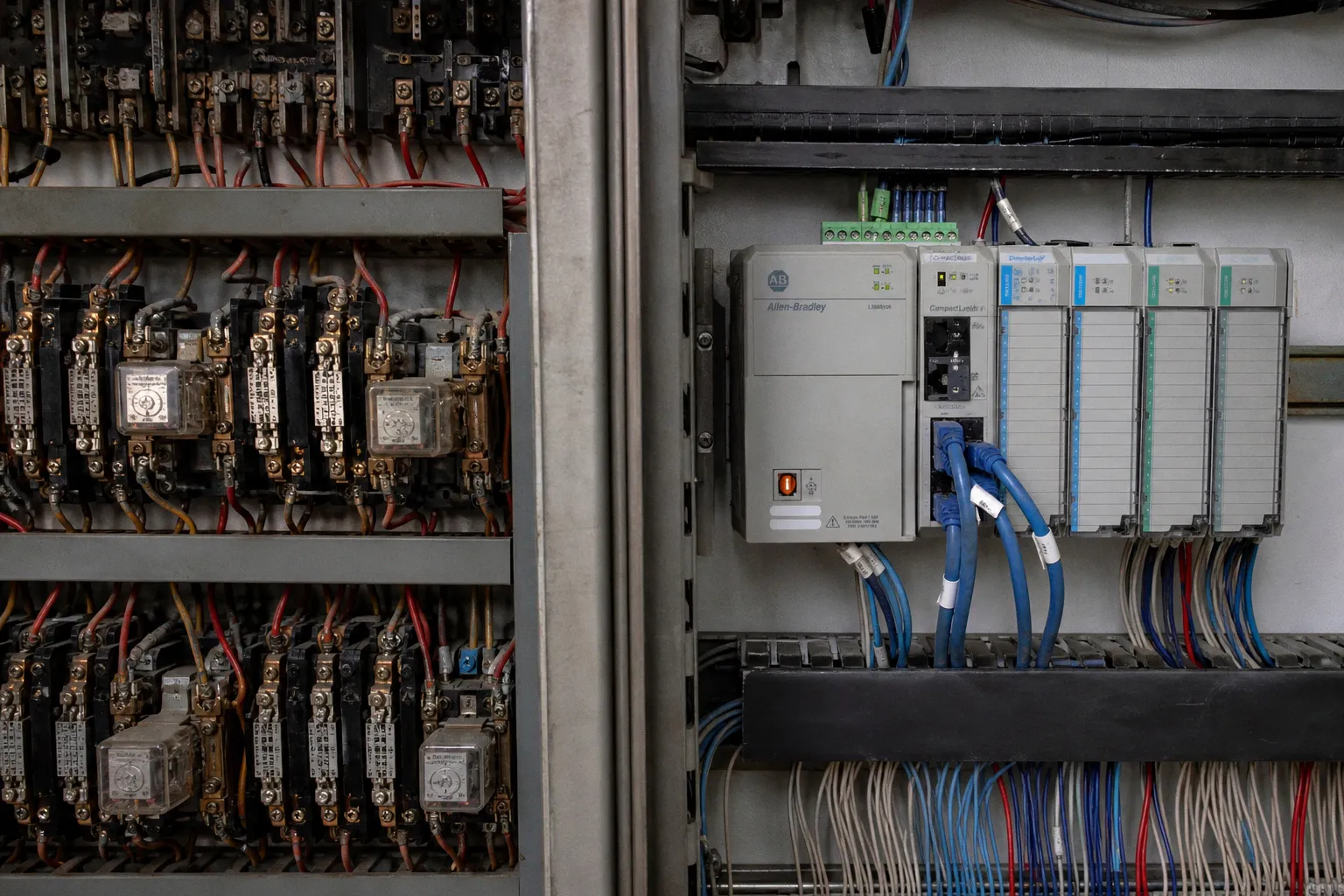
The Humming Cabinet Problem: When Wiring Becomes the Workflow
The hard part arrives when the station changes: a new level instrument replaces a float tree, a second pump needs a different alternation rule, a variable-speed drive enters the picture, or operations asks why the station has been cycling all night.
Compare car rental deals in United Kingdom
See available offersPartner link — DiscoverCars comparisonThat is where the plc vs relay logic for pump control stops being an argument about old hardware versus new hardware. Both architectures can run a pump. Both can protect a motor through the proper overload and starter circuitry. The real distinction is how each system behaves when the sequence becomes more complicated, when the maintenance record matters, and when someone needs to understand the station without standing in front of an open cabinet.
A relay cabinet makes its logic visible in copper. A PLC puts that logic in software. Neither approach excuses bad design, poor documentation, weak field instruments, or an undersized pump. But they fail differently, they change differently, and they impose very different costs over the working life of a station.
Evolution of Pump Station Architecture: From Hardwired Banks to Programmable Logic
Traditional pump station control architecture was built around physical cause and effect. A float rose, a contact closed, a relay coil energized, another set of contacts changed state, and a motor starter received a command. Lead-lag sequencing, high-level alarms, elapsed-time functions, permissives, and hand-off-auto selection all existed as real devices connected by real conductors.
That approach has virtues that should not be dismissed just because the panel is old. A well-drawn relay circuit can be read with a meter and a schematic. A technician can see a dropped-out coil, hear a relay chatter, or trace an energized control leg without a programming cable. For a simple application, that directness is often exactly what the owner needs.
The problem is accumulation. One extra requirement rarely stays one extra requirement. A timer is added for restart delay. An interlock appears because of a downstream valve. The alternation scheme changes after repeated uneven run hours. A high-high alarm must trigger a second duty mode. Someone adds remote indication. Then the cabinet becomes a record of every past decision, including the ones that were never redrawn on the schematic.
Mechanical relays also have physical limits. Contacts wear. Coils fail. Timing relays drift or become difficult to replace. Loose terminals and voltage problems create faults that can be intermittent enough to consume a maintenance crew’s day. None of this means relay logic is inherently unreliable; it means the cabinet’s reliability is tied to the condition of many individual devices and to the accuracy of its documentation.
A PLC changes the location of the logic, not the fundamentals of the pump station. Field devices still matter. Starters, disconnects, overloads, motor protection, control transformers, pilot lights, and emergency circuits still belong in the panel. The PLC reads inputs, evaluates the sequence, and commands outputs. The relay has not disappeared. It has simply been moved to the places where electrical isolation, contact rating, or motor-control duty actually require it.
A relay panel is a physical memory of every change ever made to it. A PLC program can be versioned—but only if somebody treats it like an engineering document.
The best industrial pump automation methods recognize that this is not a religious choice. A basic duplex sump with fixed setpoints may be well served by hardwired control. A station with multiple operating modes, analog instruments, remote alarms, variable-speed equipment, and recurring process changes usually benefits from a programmable controller. The dividing line is not a universal pump count. It is the lifecycle burden created by the actual sequence.
That assessment should include:
- How often operating setpoints, alternation rules, or duty modes are likely to change.
- Whether the station needs analog control from level, pressure, flow, or power signals.
- Whether operators need local HMI visibility, remote alarming, or historical trends.
- How available qualified electrical and controls support will be over the life of the installation.
- What an outage costs in labor, environmental exposure, production interruption, or overflow risk.
- Whether the owner can maintain disciplined backups, drawings, passwords, and software revisions.
A PLC is not automatically the economical choice at installation. It can become the economical choice when the sequence is expected to evolve. The opposite is also true: a sophisticated controller installed on a simple station without documentation, support, or a reason to use its capabilities can be an expensive black box.
The Mechanics of Control: Comparing Relay Logic to IEC 61131-3 Programming
People often use “ladder logic” and “relay logic” as if they mean the same thing. They do not.
A relay schematic represents a physical circuit. Each contact symbol corresponds to a real contact. Each coil corresponds to a real coil. The logic exists because current can or cannot travel through a wired path.
Ladder Diagram in a PLC is a programming language with a familiar visual grammar. It borrows the look of relay schematics because electricians and technicians already understand contacts, coils, seals, interlocks, and permissives. But the controller is not sending current through a row of drawn contacts. It is scanning input states, evaluating instructions in memory, and updating outputs according to the program.
IEC 61131-3 provides the common language framework behind much of this work. Ladder Diagram remains the most comfortable entry point for many pump-control applications, especially where the sequence is made up of discrete conditions. Function Block Diagram is useful for reusable control objects and analog functions. Structured Text can make complicated calculations, data handling, and state logic easier to maintain. Sequential Function Chart can be valuable where the process moves through clear operating stages.
The language matters less than the discipline behind it. A pump-control program should read like the station operates. Inputs need names that identify the field device and its purpose. Commands must be separated from feedback. Fault conditions should be explicit rather than implied. Manual operation should not quietly bypass the protections that matter. And the final program must match the as-built panel, not the memory of whoever commissioned it.
In hardwired logic, a typical pump start might require a high-level condition, an AUTO selector position, a healthy overload, an available motor starter, and no active lockout condition. In a relay panel, those conditions are created through series and parallel contact paths. In a PLC, they become permissive bits, status tags, and output logic. The functional intent can be identical. The maintenance experience is not.
| Dimension | Hardwired Relay Logic | PLC-Based Logic |
|---|---|---|
| Where the sequence lives | Physical wiring, contacts, timers, and relays | Controller program and configured parameters |
| Changing a sequence | Rewire, revise drawings, test under controlled conditions | Revise software, validate, download, and document the version |
| Panel growth | Increases with every timer, relay, and added condition | Mostly driven by I/O, power distribution, and field interfaces |
| Fault finding | Meter work, schematic reading, and physical inspection | Online diagnostics, tag status, alarms, trends, plus field checks |
| Analog control | Requires dedicated analog devices or separate controllers | Managed through analog I/O, scaling, and programmed control routines |
| Remote integration | Possible, but often wiring-intensive and limited | Designed for HMI, SCADA, historian, and network integration |
| Documentation risk | As-builts can drift from cabinet changes | Programs can drift too if backups and revision control are neglected |
The phrase “hardwired vs programmable logic controllers” can make the choice sound absolute. In the field, it is usually hybrid. The PLC may handle sequencing while hardwired circuits handle motor protection, control power, emergency-stop functions where applicable, and the physical means of energy isolation. Good panels use each component for the job it is suited to do.
The common mistake is treating software as though it removes the need for electrical craftsmanship. It does not. A poor termination remains a poor termination. A failed float remains a failed float. A motor starter feedback contact that does not prove run status cannot be repaired by prettier HMI graphics. PLC logic is powerful because it makes the sequence easier to observe and change. It does not repeal the laws of field wiring.
Precision and Process Optimization: Implementing PID Loops and Variable-Speed Drives
The biggest practical shift in modern pump control is often not the PLC alone. It is the PLC, a variable-frequency drive, and a usable feedback signal working as one system.
A constant-speed pump station controls level or pressure by starting and stopping equipment at fixed points. For many applications, that is appropriate. Pumps are sized for duty, floats or transmitters establish the operating band, and the station cycles through lead and lag operation as demand changes.
A VFD adds another option: rather than simply switching a pump between stopped and full speed, the controller can vary speed in response to process demand. In a wet-well application, the PLC can compare measured level with a target level and send a speed reference to the drive. In a pressure system, it can adjust pump speed to maintain pressure while demand rises and falls.
That feedback strategy is commonly expressed as PID control: proportional, integral, and derivative action. The controller measures error—the difference between the desired process value and the actual value—and adjusts output to reduce it. The concept is straightforward. Commissioning it is not.
Pump stations are not clean laboratory systems. Level signals can be noisy. Wet wells can have turbulence. A poorly placed pressure transmitter can see transients rather than useful process behavior. Check valves may chatter. A pump curve may not match the assumptions made on paper. If the loop is tuned too aggressively, the drive hunts. If it is tuned too slowly, the station feels unresponsive and may fail to keep the process within the desired operating range.
Deadband is one of the tools that keeps a control loop from reacting to every small signal movement. It is not an admission of defeat. It acknowledges that a process signal has noise and that equipment has inertia. The goal is stable control, not constant correction.
The useful question is not whether a PID loop can hold a setpoint. It is whether the sensor, pump curve, drive, and tuning allow it to hold that setpoint without making the station restless.
There are several details that separate a useful variable-speed implementation from a decorative one:
1. The feedback signal has to represent the process. A level sensor mounted where it sees splashing, foam, or unstable turbulence can make a good controller look incompetent. Signal filtering may help, but filtering cannot rescue a fundamentally poor measurement location.
2. Minimum and maximum speed limits need engineering judgment. A pump cannot always operate efficiently or safely across the entire speed range of the drive. Low-speed operation may reduce cooling or create unstable hydraulic behavior. High-speed operation may push the system beyond motor, pump, pipe, or valve limits.
3. The station still needs staging logic. One variable-speed pump may carry low and moderate demand, while an additional pump starts when demand exceeds what the lead unit can deliver. The controller has to decide when to add capacity and when to return to a lower-energy operating condition.
4. Fallback operation matters. A station should have defined behavior for failed analog input, VFD fault, communication loss, or controller failure. A good design does not wait for a fault to discover whether the pumps can still be operated safely.
5. Trend review is part of commissioning. The first stable-looking screen is not the end of the work. Operators and technicians need to watch how level, speed command, flow, starts, and alarms behave through real demand changes.
The plc advantages in water systems are especially visible here. The controller can coordinate speed control, lead-lag rotation, runtime balancing, alarm thresholds, and fault response without turning the panel into a dense collection of separate analog modules and timing relays. But a PLC does not make a VFD application automatically efficient. It makes the logic available. The pump selection, hydraulic conditions, instrumentation, and tuning still decide whether the result is graceful or noisy.
Data Integration and SCADA: Expanding Visibility in Wastewater and Industrial Systems
A relay panel can provide status. A PLC can provide context.
That distinction changes how a station is operated and maintained. With traditional relay control, an operator may know that a pump is running, stopped, or faulted if the relevant pilot lights and auxiliary contacts have been wired out. More detail means more conductors, more terminals, more interposing relays, and more opportunities for the drawings to fall behind the cabinet.
In a PLC-based station, inputs, commands, alarms, calculated values, and operating states exist as tags. An HMI can show them locally. A SCADA system can collect them remotely. A historian can turn them into trends. The information might include pump availability, run feedback, drive status, wet-well or suction level, discharge pressure, flow indication, generator status, power-related alarms, and communication health.
The point is not to put every possible bit on a screen. That approach creates the kind of alarm clutter that operators learn to ignore. The point is to give people enough information to make a better decision before they arrive at the site.
A useful pump status display does more than show a green icon. It distinguishes between:
- A pump that has been commanded to run.
- A pump that has actual run feedback.
- A pump that is unavailable because of overload, local control selection, drive fault, or maintenance lockout.
- A pump that is in automatic duty, manual operation, or an inhibited state.
- A station that has a process problem, such as rising level despite a run command.
That is the practical value of data integration. A “pump fail” alarm is a starting point. A clear alarm that identifies the failed permissive, the affected equipment, and the process consequence is something a night operator can act on.
SCADA also changes maintenance planning. Trends can reveal a station that begins to cycle more frequently, a level signal that has become erratic, a drive that spends too much time near a limit, or a pump that no longer produces the expected response. Those observations do not replace inspection. They make inspection more targeted.
A single operations team can supervise a broad group of geographically distributed stations from one environment when the communications, security, and operating standards are designed well. That does not mean every station should be remotely controlled in the same way. Monitoring and control are different decisions. Remote control introduces questions of authority, cybersecurity, site safety, communications reliability, and local operating procedures that must be resolved for each installation.
The network is also part of the pump station once SCADA is involved. Segmented industrial networks, controlled remote access, managed credentials, backups, and tested recovery procedures are no longer optional administrative extras. A controller connected to a plant network or remote telemetry system needs the same seriousness applied to it as any other operational technology asset.
Safety and Compliance: Understanding OSHA Lockout/Tagout Limitations for PLC Systems
This is where enthusiasm for automation needs to stop and become precise.
A PLC command is not an energy-isolating device. A stop button on an HMI is not an energy-isolating device. A software inhibit is not a lockout. They may prevent normal automatic operation, and they may be useful as part of a safe control strategy, but they do not provide the physical isolation required before workers perform servicing where hazardous energy is present.
For pump equipment, hazardous energy can include electrical supply to the motor and controls, stored pressure in piping, rotating equipment, gravity, flow through valves, and any other source that could create movement or exposure during maintenance. The details vary by installation. The principle does not: workers need established lockout/tagout procedures and actual energy-isolating devices that can be secured in a safe position.
The PLC belongs in the control layer. It can de-energize an output, indicate that a disconnect is open, alarm on an unexpected start signal, or help enforce an operational sequence. It cannot replace the disconnect, breaker, valve isolation, or site procedure required to protect a person working on the equipment.
That distinction needs to appear in the design itself. A safe pump control panel should make it clear which functions are process control, which are protective interlocks, and which actions require physical isolation. Local controls should not create ambiguity about whether equipment is safe to service. HMI screens should not imply that a software “off” command is equivalent to lockout. Operators and maintenance crews should know what feedback proves—and what it does not prove.
This is also one reason not to overpromise remote control. A remote operator may have accurate visibility into station status while still lacking the site conditions needed to authorize a start. Personnel may be working nearby. A valve lineup may be different from the expected position. A local selector may be in maintenance mode for a reason that does not appear cleanly in a tag list.
The strongest control system is not the one with the most automation. It is the one that makes normal operation easier while remaining honest about the limits of software.
Relay logic still earns its place in simple, stable pump applications where local serviceability and straightforward wiring are more valuable than flexibility. PLC control earns its place when the station needs evolving sequences, analog control, variable-speed coordination, meaningful diagnostics, and integration with a larger operating picture.
The decision should come from a project-specific lifecycle assessment, not from a blanket rule about how many pumps sit in the wet well. Look at the process, the expected changes, the operational consequences of failure, the people who will maintain the system, and the discipline available for documentation and software management. Then choose the architecture that makes the station easier to run, easier to troubleshoot, and harder to misunderstand.