Distributed control systems versus programmable logic controllers for plant automation
At 2:15 in the afternoon, nobody on the floor is asking whether the plant has a “modern” control platform.
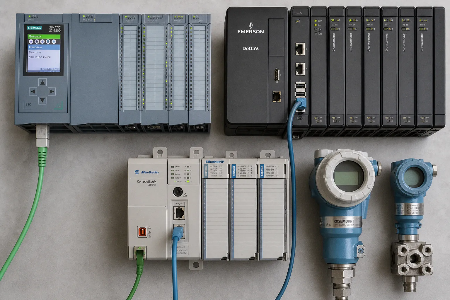
The operator is trying to understand why a discharge pressure is drifting, whether Pump 3 really received its start command, why one valve is hunting, and whether the alarm on the screen is a symptom or the beginning of a shutdown. That is where the distributed control system versus programmable logic controller architecture question becomes real: not in a vendor comparison chart, but in the seconds between a process deviation and a confident response.
Compare car rental deals in United Kingdom
See available offersPartner link — DiscoverCars comparisonWe often hear DCS and PLC described as competing choices, as though selecting one means banishing the other from the site. On the ground, that is rarely how a capable plant is assembled. A PLC may run a local pump skid, a filtration train, a packaging cell, or a valve manifold perfectly well on its own. The same PLC may also sit inside a wider distributed control system, handling field-level work while a supervisory layer coordinates production, alarms, trends, operator displays, and plant-wide setpoints.
The useful question is not “DCS or PLC?” It is: where does control need to live, who needs to see it, and what happens to the operator’s work when one piece of the system becomes unavailable or unclear?
Plant-level control hierarchies are where the distinction begins
A programmable logic controller is a programmable industrial controller with memory for logic, timing, counting, communications, arithmetic, data handling, I/O control, and PID functions. This is why the PLC remains such a durable piece of plant hardware. It can receive a 4–20 mA pressure signal, start a motor through a variable-frequency drive, sequence duty and standby pumps, calculate a flow total, close a valve on a high-high trip, and communicate that status to an HMI.
For a contained process, this can be all the architecture you need.
A distributed control system, by contrast, is a plant-level supervisory architecture. It organizes control across multiple distributed controllers and brings their process information into a coordinated operating environment. In the topology described by NIST, a control server or supervisory controller exchanges information with distributed field controllers over a control network. It sends requests and setpoints; the local controllers act on those commands and on the feedback arriving from field sensors.
That hierarchy matters because physical processes do not all have the same operating rhythm.
A small lift station with several pumps may have one local PLC, a compact operator panel, and a remote monitoring connection. If the process is straightforward, the team knows the equipment intimately, and the main task is dependable local sequencing, this can be an honest, serviceable architecture. There is no prize for installing a plant-wide platform where the daily reality does not call for one.
Now move to a water treatment facility with intake, coagulation, filtration, chemical dosing, clearwell management, high-service pumping, sludge handling, and several remote sites. You have many local control decisions, but you also have shared production targets, interlocks that cross area boundaries, alarm priorities, coordinated operator actions, and a need to understand the state of the whole plant rather than one cabinet at a time. That is where a DCS-shaped architecture begins to earn its place.
| Architectural question | PLC-centric plant control | DCS-oriented plant control |
|---|---|---|
| Primary control focus | Local machine, skid, cell, or contained process | Coordinated operation across multiple process areas |
| Control hierarchy | Often controller and local HMI, with optional supervisory additions | Supervisory layer coordinating distributed controllers |
| Operator experience | Can be highly effective locally; consistency depends on implementation | Usually designed around a shared plant operating environment |
| Expansion pattern | Add controllers, panels, networks, and software integration as needed | Add distributed control areas within a common architecture |
| Role of PLCs | Can be the primary controller | Can serve as local or field controllers within the larger system |
| Fault containment | Depends on the design of the individual system and connections | Modular distribution can reduce the effect of a single fault across the overall architecture |
The final row needs careful reading. A DCS does not guarantee uninterrupted operation, and no architecture becomes resilient merely because its product label says “distributed.” But modularizing a production system can reduce how widely one fault reaches. That is a meaningful architectural advantage when a plant is made of many interdependent areas, each with its own instrumentation, actuators, and operating responsibility.
The architecture is working when the operator can see the plant as one process without losing the tactile reality of the equipment in front of them.
For us, the most revealing early question is this: if a local controller loses communications with the supervisory layer, what should continue happening safely and intelligibly? If the answer is “the local loop must hold pressure, maintain level, or complete a safe sequence,” then the field control needs genuine autonomy. If the answer is “the operator needs a plant-wide view before making the next decision,” then the supervisory experience needs just as much design attention as the controller code.
A network layout changes more than wiring
The distributed control system network layout is frequently drawn as a clean stack: field instruments at the bottom, controllers in the middle, servers and operator stations above. That drawing is useful, but it can hide the physical work inside the plant.
Every pressure transmitter, valve positioner, VFD, flowmeter, motor starter, and remote I/O island has to be installed, powered, labeled, commissioned, diagnosed, and eventually serviced by someone wearing gloves in a noisy environment. A network decision affects all of that. It affects cable routes, cabinet heat, spare parts, commissioning time, diagnostic visibility, and the number of moments when an operator or technician has to ask, “Which device is this alarm actually talking about?”
Traditional point-to-point wiring gives a controller a dedicated electrical relationship with each signal. It is familiar and direct, and it may be entirely appropriate for a smaller PLC panel with modest I/O. But it also grows physically: more instruments mean more terminations, more marshalling, more cable management, and more opportunities for a documentation gap to become a troubleshooting delay.
Fieldbus networks alter that layout. In the DCS example documented by NIST, fieldbus communication removes the need for individual point-to-point wiring between the controller and every sensor or actuator. Depending on the system design, the network can also expose device diagnostics and support control functions in the field rather than sending every decision back through a central controller.
That is not a blanket instruction to replace hardwired I/O with a bus network. It is an invitation to be precise about the job.
If the field device is a simple discrete level switch whose only responsibility is to prevent a dry-running pump, then a direct hardwired path may be exactly the clarity you want. The signal is legible, testable, and independent of several layers of network configuration.
If the device is a smart valve positioner on a critical process line, then diagnostics about travel, air supply, position error, or device condition may materially improve maintenance work. In that case, a networked device architecture can give the crew more than a binary “open/not open” story.
We should also be honest about the operational cost of sophistication. A field network gives you a richer device model only if the team can commission it, document it, maintain it, and interpret the diagnostics without creating alarm fatigue. A screen full of device alerts that no one trusts is not visibility. It is noise with a timestamp.
Design the network around decisions, not around fashionable protocols
When we map a control system architecture comparison, we usually walk the process in this order:
1. Identify which decisions must remain local. A pump protection trip, a rapid shutdown sequence, or a pressure-control loop should not depend on a distant business system, cloud service, or a casual remote connection. Local control remains local because the physical process does not pause while the network recovers.
2. Separate process control traffic from everything that merely wants data. A historian, dashboard, maintenance application, digital twin, and reporting platform may all be useful. They should not be allowed to blur the network boundaries that keep deterministic control understandable and supportable.
3. Decide what diagnostics change action. If a smart instrument’s diagnostic tells maintenance what to inspect before a failure, it earns its place. If it only adds another warning without a defined response, it may increase operator fatigue rather than reduce it.
4. Plan for commissioning and replacement. The original project team will not be the only people touching the system. Think about the technician replacing a failed drive at 5 a.m. Can they identify the device, restore the configuration, and confirm normal operation without archaeology?
5. Give remote access a specific operational purpose. Remote monitoring and remote control are not interchangeable. Viewing trends from a secure operations center is one thing; issuing a start command to rotating equipment is another. The architecture needs to make that distinction visible, deliberate, and defensible.
This is where both DCS and PLC designs can fail in the same way: they become collections of technical capabilities rather than tools shaped around real-world context. A plant does not benefit from “connectivity” in the abstract. It benefits when the right person can make the right decision with enough information and enough control authority to act safely.
Programming is not just a developer choice
The programming discussion can become unnecessarily tribal. Some teams speak as though Ladder Diagram belongs to an older generation, while others treat Structured Text as proof that an application is more advanced. Neither view helps the person who has to troubleshoot a sequence after a shift change.
IEC 61131-3:2025 defines the core programmable-controller languages Structured Text, Ladder Diagram, and Function Block Diagram, while also defining Sequential Function Chart elements for organizing programs and function blocks. These are not merely syntax preferences. Each can make a different part of a physical process easier to read.
Ladder Diagram still maps naturally to many discrete conditions: permissives, interlocks, motor starts, fault latching, and hardwired-style logic. A maintenance electrician can often follow a rung in a way that resembles tracing a circuit, which provides useful tactile feedback even when the circuit itself is now software.
Function Block Diagram is often comfortable for analog control and reusable process objects. A pump control block, PID loop, valve control block, or VFD interface can gather the expected signals and behaviors in one recognizable form. When you have many similar assets, this can make consistency easier to maintain.
Structured Text is powerful for calculations, data manipulation, complex algorithms, and logic that becomes awkward when stretched across many graphical elements. It should not be treated as a magic upgrade. If the local support team cannot read or test it comfortably, a beautifully written routine may become an opaque box at exactly the wrong moment.
Sequential Function Chart is especially useful when the process has clear states: fill, mix, hold, drain, wash, standby, fault recovery. It helps the team see the operational sequence rather than only the individual conditions underneath it.
The choice is rarely one language for the whole plant. The stronger practice is to use each form where it makes behavior visible to the people who will live with it.
In a PLC-centric system, the application structure may be shaped largely by the integrator’s conventions and the controller platform. In a DCS, the engineering environment often emphasizes standardized control modules, faceplates, alarm behavior, graphics conventions, and shared configuration patterns across process areas. That can make large systems more coherent, but only if the standards are humane rather than bureaucratic.
If-then logic is useful here. If one operator moves from raw water to filtration to high-service pumping during a shift, then a pump faceplate, alarm presentation, and manual control behavior should feel familiar across those areas. If every controller is delivered as an independent island with its own naming, colors, and control quirks, then the operator spends attention translating interfaces instead of understanding the process.
Standardization is not about making every screen look identical; it is about ensuring that identical actions produce familiar feedback wherever the operator stands.
This is also why HMI design cannot be an afterthought attached after the PLC logic is complete. The operator’s screen is part of the control loop. It is where a command becomes confirmation, where a trend becomes a diagnosis, and where alarm priority either supports action or creates fatigue.
Enterprise integration is a boundary, not a shortcut
Plants increasingly want production data in maintenance systems, quality systems, reporting tools, energy platforms, and business planning environments. That desire is legitimate. A plant manager needs to know more than whether a pump is running; they may need to understand energy use, runtime distribution, maintenance exposure, throughput, and the reason production capacity was constrained.
But enterprise integration should not flatten the distinction between operational technology and business technology.
ISA-95, also designated IEC 62264, provides a technology and business-process architecture for integrating enterprise and control systems. Its Level 3 to Level 4 interface addresses the connection between manufacturing operations and business systems. In plain language: there is a meaningful boundary between running the plant and planning, accounting for, or optimizing the business around it.
A DCS may provide a more natural foundation for broad plant supervision and integration because it already organizes multiple process areas under a common control environment. Yet a PLC-based system can also feed historians, HMIs, SCADA platforms, maintenance software, and enterprise applications. The difference is not a yes-or-no capability question. It is how much architecture, interface design, data governance, and lifecycle ownership you are prepared to build around it.
That distinction becomes especially visible when a plant starts talking about industrial IoT, digital twins, or remote operations. These are not features you switch on because a controller has an Ethernet port. They require selected data, known context, reliable naming, network segmentation, access control, maintenance responsibility, and a clear answer to the simplest question: what operational decision will this information improve?
For example, a digital representation of a pump station may be valuable if it connects live pressure, flow, vibration, runtime, drive status, and maintenance history in a way that helps a team anticipate a service issue. It is less useful if it becomes a glossy duplicate of the plant that nobody consults during an actual upset.
NIST’s operational technology guidance is helpful in spirit here: control environments have consequences beyond data loss. Availability, integrity, safety, equipment condition, and physical process behavior all sit close together. That is why remote access, cloud connections, and enterprise interfaces belong in the architecture conversation from the beginning, not as a late-stage request from a dashboard project.
Choosing the route without inventing a magic threshold
There is no universal I/O count, plant size, loop count, or budget number at which a DCS automatically becomes the correct answer. Any claim that says otherwise is selling a shortcut. A compact but operationally critical process may need disciplined supervisory architecture; a larger but highly modular site may be well served by coordinated PLC and SCADA layers.
Instead, we can use the shape of the work as a guide.
A PLC-led architecture is often a strong route when the process is localized, sequences are contained, local autonomy is the priority, and the people supporting the plant need direct access to a manageable controller and panel environment. This is common for packaged equipment, pump skids, booster stations, standalone machine areas, and incremental upgrades where replacing the entire control ecosystem would create more disruption than benefit.
A DCS-oriented route deserves serious consideration when multiple process areas must operate as a coordinated whole, when operator stations need a shared view of alarms and process state, when standard control objects and graphics will reduce variation, and when the plant needs to grow without turning into a patchwork of unrelated HMIs and controller projects.
The hybrid route is often the most realistic. Local PLCs manage package systems, specialist skids, or discrete equipment. A supervisory DCS or comparable plant-level environment coordinates the broader process. The architecture respects the fact that equipment has local needs while operations has plant-wide needs.
The best system is not the one with the longest feature list. It is the one that lets a technician trace a signal without guessing, lets an operator understand a process deviation before it becomes a crisis, and lets the plant expand without asking people to memorize a new control philosophy every time another cabinet arrives.
When we get that right, the daily improvement is quiet but substantial: fewer ambiguous alarms, less operator fatigue, less hunting through screens for a simple answer, and more confidence that the control system is standing beside the people who run the plant rather than making them work around it.