PLC control cabinet layout: pre-installation engineering checklist for industrial panels
Most teams treat the PLC control cabinet as furniture. Pick an enclosure that looks roughly right, slot in the components, terminate the wiring, ship.
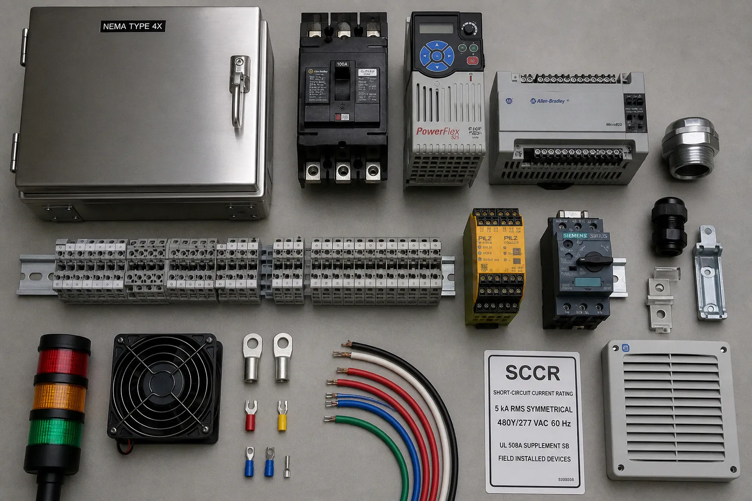
Six months later, something drifts: a fault-current assumption turns out to be wrong, a heat-soaked analog input starts lying about its reading, or a remote-access port nobody documented becomes the diagram on a breach post-mortem.
I have audited enough of these panels to tell you, with no exaggeration, that the cabinet is where the engineering either happens or quietly does not. A plc cabinet layout design pre deployment checklist is not paperwork attached to the real job. It is the part of the real job that forces the electrical, mechanical, controls, operations, and cybersecurity decisions to meet in one place before the panel is energized.
The useful version is jurisdiction-sensitive, component-specific, and deliberately unsentimental. Available fault current, SCCR, enclosure rating, cooling, clearances, cable separation, and remote access do not yield to universal answers. They yield to a documented evaluation of the actual assembly and the actual place where it will live.
Evaluate available fault current and SCCR before you cut a single DIN rail
The first number the panel owes you is the available fault current at the line terminals of the machine supply-circuit disconnecting means. Not the interrupting rating printed on a breaker. Not an old transformer value copied from a one-line diagram. Not a number carried over from the previous project because the building “has the same service.”
It is the available fault current at the specific point of connection, under the applicable supply conditions, with the utility contribution and upstream system characteristics properly considered.
NEC Article 409 requires industrial control panels to be marked with a short-circuit current rating, or SCCR. That SCCR must be suitable for the available fault current at the panel’s point of installation. This is the point where a neat panel layout can become an unsafe panel: a control system may be perfectly functional at normal load and still be improperly rated for a fault condition.
UL 508A Supplement SB provides an accepted method for establishing SCCR for many industrial control panel assemblies. The important word is assembly. An SCCR is not a decorative maximum borrowed from the highest-rated protective device in the bill of materials. It is established through the applicable evaluation of the actual components, their ratings, their use in the circuit, and any recognized combination ratings or current-limiting protection arrangements.
Terminal blocks are a frequent source of trouble. Under UL 508A Supplement SB, a terminal block may carry a default SCCR that is lower than the values attached to upstream breakers, disconnects, or drives unless a higher rating is established by the applicable method. That does not mean every panel containing a particular terminal block automatically receives one fixed SCCR. It means the designer has to evaluate how that terminal block is used in the specific assembly, what protective device is ahead of it, and whether the intended rating is supported by the component documentation and the Supplement SB process.
A panel’s SCCR is not a trophy awarded to its best component. It is a documented rating for the assembled panel in its intended circuit.
Do not reduce this to component arithmetic. A breaker with a high interrupting rating does not, by itself, prove the SCCR of every downstream assembly. Nor does the lowest nameplate value always settle the matter without considering the circuit construction, the protective device, and the manufacturer’s recognized ratings. The correct conclusion comes from the specific SCCR evaluation, not from an argument in the aisle next to the DIN rail.
Before release, the design file should answer a few plain questions:
- What available fault current is expected at the installation point?
- What SCCR is being marked on the completed panel?
- Which method and component data support that mark?
- Are branch circuits, feeder circuits, power supplies, drives, terminal blocks, and control transformers evaluated in their actual arrangement?
- Is any current-limiting or series-rated approach being relied upon, and is it documented exactly as required?
- Has the final design been reviewed against the installation conditions and the authority having jurisdiction?
The last question matters. A panel shop can perform its evaluation correctly and still be handed incomplete site data. The site engineer can know the available fault current and still receive a panel whose mark was built around a different configuration. This is why SCCR needs to be settled while the layout is still editable, not after the cabinet has been wired, labeled, and loaded onto a truck.
Pick the enclosure for the environment, not for the catalog page
The enclosure is not a box with a rating badge. It is the boundary between the equipment and the real world: dust, washdown, sunlight, airborne contaminants, steam, vibration, corrosion, insects, hose spray, ambient heat, and whatever maintenance culture the site has developed over the years.
NEMA Type 4X is often discussed as though it were the universal answer for harsh industrial locations. It is not. It describes a specific protection profile, including protection associated with outdoor exposure, water ingress, corrosion resistance, and hose-directed water. That may be appropriate. It may be unnecessary. It may also be insufficient for a particular chemical atmosphere, washdown regime, temperature cycle, or installation method.
A chemical dosing area is a good example of why slogans fail. The presence of chemicals does not automatically determine a single enclosure type or material. The assessment must identify the actual agents, their concentration and form, whether exposure is splash, vapor, residue, or washdown, the cleaning process, the expected duration of exposure, and the enclosure material’s compatibility data. A stainless enclosure can be a sensible choice in one process area and the wrong choice in another. A nonmetallic enclosure can resist one contaminant while creating different thermal, UV, mechanical, or grounding considerations.
The enclosure decision should be made from the environment outward:
- Dry indoor control room, process floor, outdoor rack, food area, wastewater gallery, chemical skid, or mobile machine installation.
- Dust characteristics and whether the dust is ordinary, conductive, combustible, or merely annoying until it blocks every filter.
- Water exposure: dripping, splashing, hose-down, washdown frequency, condensation, or wind-driven rain.
- Corrosive agents and cleaning chemicals, checked against the enclosure manufacturer’s compatibility information.
- Ambient temperature, solar loading, altitude where relevant, and seasonal variation.
- UV exposure, mechanical damage risk, vibration, and the practical need to open the cabinet during service.
- The need for viewing windows, operator devices, cable entry systems, ventilation hardware, and cooling equipment that may affect the effective protection of the finished assembly.
This is where industrial enclosure thermal management stops being a separate calculation and becomes part of the enclosure decision. A sealed cabinet protects against contamination, but it also removes the easy escape route for heat. A vented cabinet may cool well, but it can be a bad fit for dust, washdown, or corrosive air. An air conditioner solves some heat problems and adds maintenance, condensate, power demand, and another failure mode. A heat exchanger is not a magic word either; it depends on the temperature difference available across it and the condition of the external environment.
ABB’s cabinet-planning guidance is right about the underlying discipline: allow space for cooling airflow, required equipment clearances, cables, cable support structures, and the heat generated by the equipment actually installed. A thermal calculation that counts only the large components on the BOM and ignores power supplies, drives, network equipment, cable losses, and expansion margin is a calculation designed to make everyone feel better.
For some large cabinet drives, manufacturers specify clear free space above or around the equipment. Those dimensions are equipment-specific. They should be applied where the relevant manufacturer requires them, not copied into every PLC enclosure layout as folk wisdom. The cooling arrangement must be based on component losses, actual ambient conditions, enclosure construction, airflow path, installed accessories, and the manufacturer’s derating guidance.
A fan is not a thermal design. A thermal design is a documented path from internal heat load to allowable component temperature.
A clean layout makes this easier. Put the heat-producing devices where their heat can leave without passing through the most temperature-sensitive electronics. Keep cable ducts from becoming walls across the intended airflow path. Do not fill the upper third of a cabinet with spare wire coil and then wonder why the top-row relays age badly. Leave realistic room for future modules, but do not call empty volume “thermal margin” unless the airflow and heat transfer actually support that claim.
Working space and dedicated electrical space are not “we’ll fix it during install”
The cabinet does not become serviceable because it has a handle and a door. It becomes serviceable because a technician can approach it, open it, isolate it, inspect it, test it, and replace a component without climbing over process equipment or standing in a storage area.
OSHA 29 CFR 1910.303 establishes requirements for working space around electrical equipment. The clear working width in front of electrical equipment must be the equipment width or 30 inches, whichever is greater, and doors or hinged panels must be able to open at least 90 degrees within that working space. The working area is not overflow storage for spare motors, drums, pipe fittings, or the ladder that “will only be there for a minute.”
For specified indoor electrical equipment, dedicated electrical space requirements also need to be considered. The point is not to memorize a dimension and declare victory. The point is to reserve the space needed for safe access and to prevent foreign systems, structures, or storage practices from compromising that access after installation.
The layout review should include the actual field location, not just a cabinet elevation. Verify the wall, floor, plinth, adjacent process equipment, overhead obstructions, cable-tray route, door swing, and the path a person takes while carrying a replacement power supply or laptop. A cabinet may fit in the architectural slot and still fail the serviceability test.
For machine electrical equipment, IEC 60204-1 is central to the conversation. It covers electrical, electronic, and programmable electronic equipment and systems for machinery from the machine electrical equipment’s point of supply connection. Its concerns reach well beyond a cabinet’s physical shape: protection against electric shock, overcurrent protection, EMC, conductor and cable practices, emergency stop functions, and the interface between the control system and the machinery it governs.
The practical mistake is treating “IEC 60204 compliant” as a sentence rather than a traceable design position. If the cabinet serves a machine, the applicable requirements should map to actual decisions: disconnecting means, protective bonding, conductor identification, protective measures, emergency-stop architecture, drive safety functions, access, markings, and documentation. If the installation is a fixed process panel in the United States, NEC and the applicable local requirements may frame the work differently. The authority having jurisdiction is not a footnote to be discovered at commissioning.
Wiring separation is a design problem, not an inherited superstition
Control panel wiring standards are full of sensible principles that get damaged when people turn them into universal distances. “Keep power away from control” is useful. “All control wires must be exactly this far from all power wires” is usually where the trouble begins.
The electrical noise problem is specific to the equipment. A VFD output cable is not the same noise source as a 24 VDC feeder. An analog signal loop is not as tolerant as a discrete input. An Ethernet cable may behave differently depending on the network hardware, shielding system, grounding arrangement, cable construction, and route. The severity of coupling depends on cable length, parallel routing, switching characteristics, current, frequency content, termination, shielding, grounding, and the susceptibility of the receiving device.
So plc wiring separation rules should begin with segregation by function, then be refined using the manufacturer guidance for the actual devices and cables involved.
A workable cabinet architecture usually separates these families:
| Circuit family | Layout intention | Typical concern |
|---|---|---|
| Incoming AC and branch power | Keep close to protective and switching devices; route deliberately | Fault energy, heat, service access |
| VFD input and especially motor output conductors | Give a dedicated route where practical | High-frequency switching noise and induced interference |
| 24 VDC distribution | Keep organized and protected by load group | Voltage drop, fault isolation, mixed criticality |
| Analog and low-level signals | Use protected routes and appropriate cable practices | Noise pickup, measurement drift |
| PLC I/O and communications | Keep clear of aggressive power paths | Data errors, nuisance faults, intermittent diagnostics |
| Safety-related circuits | Route and document in line with the safety design | Integrity, traceability, maintenance error prevention |
The discipline is simple even when the geometry is not. Use separate wireways where the layout allows. Use metal barriers or segregated routing where required by the equipment guidance or justified by the noise assessment. Cross power and sensitive signal routes at approximately 90 degrees where crossings are unavoidable. Avoid long parallel runs between sensitive circuits and high-noise conductors. Give VFD output cables their own route rather than treating them as ordinary motor leads.
For analog circuits, use the cable type and shield termination method specified by the device manufacturer and the control-system design. “Ground the shield at one end” is often good advice in a particular installation, but it is not a substitute for reading the requirements of the instrument, I/O module, and system grounding scheme. The drawing should show the intended shield termination point. A shield left as an undocumented field decision is an invitation to create ground-loop problems one technician at a time.
Some manufacturer documentation identifies particular risks for long, close parallel runs of control and power cables. For example, guidance may describe a defined cable length condition and recommend a stated separation or physical barrier for a named device family. Use that guidance when it applies to the specific equipment and installation. Do not convert a product-specific length threshold into a universal rule for every PLC cabinet, every cable type, or every facility.
Where guidance is absent or the application is unusually sensitive, the answer is not to invent certainty. Review the routing, select suitable cable and shielding practices, consider physical separation or barriers, and validate the result during commissioning. If the process cannot tolerate intermittent analog noise, communication dropouts, or nuisance trips, then the design needs evidence—not a sentence copied from a previous panel.
Remote monitoring belongs in the cabinet design, along with lockout
Remote connectivity is often added to a panel in the least engineered way possible: a modem appears late in the project, someone asks for a port on the outside of the enclosure, and the network boundary becomes “whatever IT approves later.” That is not remote monitoring. That is a loose end with an antenna.
If the cabinet includes remote monitoring, remote support, cloud connectivity, or any path into operational technology, the access architecture needs to be decided before deployment. CISA guidance for internet-accessible industrial control systems and remote-access technologies emphasizes reducing exposure and using multifactor authentication where possible, including at the jump-host level.
In layout terms, this has physical consequences. The modem, managed switch, firewall, VPN appliance, industrial gateway, or remote-access device needs a defined location, power source, heat budget, grounding approach, service access plan, and network role. The panel drawing should make clear where the OT network boundary sits, how external access is brokered, who is allowed in, how sessions are authenticated, and what gets logged.
A useful pre-deployment review asks:
1. Is remote access needed for monitoring only, or does it permit control actions and programming access?
2. Does the architecture avoid direct exposure of PLCs, HMIs, and drives to the internet?
3. Is access mediated through an appropriate segmented path, such as a managed remote-access environment or jump-host arrangement?
4. Are authentication, authorization, account ownership, and session logging defined?
5. Can remote access be disabled or isolated during maintenance, incident response, or a change in site ownership?
6. Does the layout allow the network equipment to be serviced without disturbing unrelated control wiring?
Energy isolation belongs in the same conversation because access changes do not remove physical hazards. OSHA requires an energy-control program where unexpected energization, start-up, or release of stored energy could injure workers. For a PLC cabinet, that means the disconnecting means, lockout provisions, stored-energy hazards, discharge intervals where applicable, and verification procedures have to be understood before commissioning.
Drives, UPS systems, DC power supplies, pneumatic interfaces, and machine motion systems can all create assumptions that are dangerous if left implicit. A disconnect handle is a component. A lockable disconnect with accurate labels, documented isolation steps, identified stored-energy conditions, and a workable verification procedure is an engineered maintenance arrangement.
The pre-deployment review I actually run
I do not pretend this is a one-page exercise. It is an engineering record, and it has to contain actual project values rather than inherited defaults. But this is the sequence I want resolved before the panel is released.
1. Establish the installation point and fault-current basis. Confirm available fault current at the intended connection point, then determine and mark the panel SCCR using the applicable assembly evaluation. Do not use a component rating as a substitute for the completed-panel assessment.
2. Match the enclosure to the assessed environment. Select the enclosure type, material, gasket system, entries, and accessories from the actual exposure conditions and manufacturer guidance. A rating is not a universal answer to water, corrosion, dust, heat, and chemical exposure.
3. Close the thermal design. Account for installed component losses, ambient conditions, enclosure construction, airflow restrictions, cable volume, and manufacturer derating information. Confirm that the chosen cooling approach supports the actual assembly, not the brochure version of it.
4. Prove access in the field location. Put the cabinet, door swing, working space, dedicated space where applicable, cable routes, and overhead constraints on the installation drawing. Do not make the site crew discover a clearance conflict after the panel is built.
5. Define cable segregation by circuit behavior. Separate power, VFD output, control, analog, communications, and safety-related wiring in a way that reflects the actual components and manufacturer instructions. For long parallel runs or sensitive circuits, use the applicable product guidance or a project-specific assessment rather than a universal distance rule.
6. Draw the OT access boundary. Identify every remote-access component, its power and thermal load, its physical position, its network path, its authentication method, and its ownership. “Remote monitoring” is not a requirement until these things are defined.
7. Make isolation possible in the real cabinet. Confirm lockout capability, labeling, stored-energy controls, discharge considerations, and verification procedures. Then make sure a person can actually perform those steps safely in the installed location.
Do the actual engineering: the actual assembly, the actual environment, the actual cable routes, and the actual installation point.
If the panel is part of industrial machinery, trace the design against the applicable machine requirements, including IEC 60204-1 where it governs the work. If it is a fixed industrial control panel in the United States, NEC Article 409 and the applicable UL 508A approach are foundational references. If the authority having jurisdiction requires additional conditions, those conditions belong in the design before the panel is built.
The job of the pre-deployment checklist is not to make the engineering look official. It is to make the decisions happen in the right order, with evidence behind them, before anyone energizes a circuit. Everything else is noise.