Chemical pump material errors: bypassing the corrosion trap
Chemical pump failures are routinely assigned to “wrong material.” That diagnosis is incomplete.
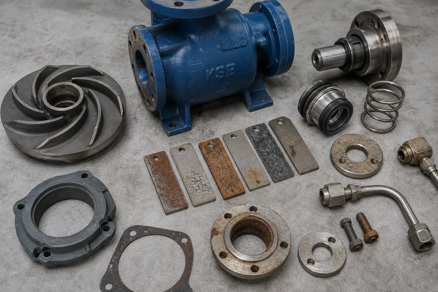
The actual failure chain usually begins earlier: a compatibility chart is read as a final specification, a casing alloy is treated as the whole wetted assembly, or nominal fluid chemistry is accepted without its temperature, contaminants, solids, and upset conditions.
This is the central pattern behind chemical pump material selection mistakes. The pump may run through commissioning, meet nominal throughput, and still enter a corrosion path that was present in the specification from day one. The error rate rises when material selection is handled as a catalog filter rather than a system-level constraint analysis.
A corrosion-resistant casing does not compensate for an incompatible O-ring. A suitable alloy in clean liquid does not remain suitable beneath deposits or in a stagnant seal chamber. A material chart tested at 70°F does not describe a hot batch process, a CIP cycle, or an unplanned concentration excursion.
Material selection is not a casing decision. It is a wetted-path decision under actual process conditions.
The 70°F Trap: Compatibility Data Is a Boundary, Not Approval
Chemical-resistance tables are useful. They reduce the search space. They do not approve a pump for service.
One widely used chemical resistance guide states that its ratings assume pumped-fluid temperatures of no more than 70°F. That condition matters. Corrosion rates can shift sharply with higher temperature, different concentration, or trace elements in the process liquid. A chart entry marked “resistant” is therefore a conditional observation, not a universal material guarantee.
The selection process fails when a specification contains only the chemical name. “Sulfuric acid,” “caustic,” “solvent,” or “brine” does not describe a pump duty with enough resolution to select aggressive media pump materials.
The actual input set needs to define:
- Chemical composition, including mixture components rather than the trade name or primary ingredient alone.
- Normal concentration and the concentration range during batch changes, evaporation, cleaning, and process upset.
- Minimum, normal, maximum, and transient fluid temperature.
- Suction and discharge pressure, plus vacuum exposure where relevant.
- Dissolved gases, oxidizing agents, chlorides, catalysts, cleaning residues, and trace contaminants.
- Expected operating hours, start-stop frequency, standby duration, and flushing regime.
- Solids content, particle hardness, particle size, and settling tendency.
- Required flow range and minimum continuous stable flow, because low-flow recirculation can raise local temperature and change exposure conditions.
This is not documentation overhead. It is the minimum dataset required to reduce selection latency and prevent the engineering team from comparing materials against an undefined duty.
A process stream at 70°F and a process stream at 140°F are not adjacent points on the same compatibility decision. They may have different corrosion mechanisms. A diluted acid may be manageable during normal operation but become substantially more aggressive after process concentration changes. Trace halides can invalidate an otherwise plausible stainless-steel choice. Cleaning chemicals can attack materials that tolerate the production liquid.
The common procurement shorthand — “316 stainless chemical pump” — creates false confidence because it compresses too many variables into one label. It describes an alloy family. It does not describe chloride level, weld condition, crevice geometry, seal configuration, or fluid temperature.
A better input model for the material review
| Process variable | Weak specification | Usable specification input | Failure mode avoided |
|---|---|---|---|
| Fluid identity | “Acid solution” | Full composition and concentration range | Incorrect general-corrosion rating |
| Temperature | “Ambient” | Normal, maximum, upset, and cleaning-cycle temperatures | Elevated corrosion rate |
| Contaminants | Not listed | Chlorides, oxidants, dissolved solids, residual cleaners | Pitting and unexpected chemical attack |
| Pressure | Discharge pressure only | Suction, discharge, seal-chamber, vacuum, and transient pressure | Seal and secondary-element mismatch |
| Solids | “Clean liquid” | Percent by weight or volume, maximum particle size, hardness | Erosion and deposit-driven corrosion |
| Operating profile | Continuous | Batch, standby, flush, recirculation, dry-run exposure | Stagnant-zone and temperature-excursion damage |
The throughput consequence is direct. A pump selected on a nominal chart may retain hydraulic performance initially, then lose head as clearances expand, internal recirculation rises, or impeller surfaces erode. The material error becomes a process-control error.
Beyond the Casing: The Wetted Assembly Is the Unit of Analysis
Pump housing material compatibility is necessary. It is not sufficient.
Chemical-resistance references often cover only cast-metal components such as the casing and impeller. Plastics, elastomers, engineering ceramics, seal faces, springs, fasteners, sleeves, and gaskets sit outside that narrow scope. Treating a casing chart as coverage for the complete pump creates a predictable blind spot.
A chemical pump is a material stack. Each material has its own exposure, stress state, temperature, and geometry.
For a standard centrifugal pump, the review should include at least:
1. Casing and cover
These components carry the main pressure boundary. They are exposed to bulk-fluid chemistry, but also to localized flow effects, deposits, and crevices at joints.
2. Impeller and wear components
These see high local velocity, particle impact, pressure gradients, and sometimes cavitation. A material that survives static immersion may fail under erosion-corrosion conditions.
3. Shaft and shaft sleeve
These components can be exposed through leakage paths, seal-chamber circulation, or vapor-phase conditions. Their material must also be compatible with the selected seal hardware.
4. Mechanical seal faces
Face materials are selected for tribological behavior as well as chemical resistance. The seal interface is not a passive wetted surface. It generates heat and operates under contact pressure.
5. Secondary seal elements
O-rings, gaskets, wedge rings, and bellows materials are separate design decisions. Temperature, pressure, chemical compatibility, and seal design all change their operating envelope. There is no universal elastomer or polymer selection.
6. Springs, drive hardware, and fasteners
These are frequently omitted from early material reviews. They are also frequent sites of crevice geometry, galvanic coupling, and stress concentration.
7. Auxiliary pipework and flush components
Seal plans, flush lines, restriction orifices, valves, and instrumentation can introduce a different alloy or polymer into the same process path.
The cognitive load rises when this work is distributed between process engineering, pump procurement, seal vendors, and maintenance. Each group may approve its own component. No one may own the assembled wetted path. That is a system design failure.
A useful specification does not say “all wetted parts compatible.” That phrase has low information value and high ambiguity. It identifies each exposed component, its material, and its service condition.
The pump fails at the weakest exposed component, not at the most expensive alloy in the bill of materials.
Chlorides: General Corrosion Data Does Not Cover Localized Attack
Stainless steel is often selected because the general corrosion rate appears acceptable. This is one of the more expensive shortcuts in industrial pump corrosion resistance work.
Localized corrosion follows a different logic from uniform wall loss. A component may look acceptable in an immersion table and still suffer pitting or crevice corrosion when chlorides, oxidizing conditions, elevated temperature, acidity, deposits, or stagnant areas are present. Weld defects and heat tint can further reduce resistance in the affected zone.
The distinction matters operationally:
- General corrosion reduces wall thickness across a broad surface. It is often observable and, in some cases, predictable through corrosion allowance.
- Pitting corrosion produces concentrated penetration at discrete points. It can perforate a component with little overall metal loss.
- Crevice corrosion develops in shielded, low-oxygen areas. Gasket interfaces, lap joints, deposits, threaded regions, and fastener heads are standard risk locations.
- Erosion-corrosion combines fluid velocity or solids impact with chemical attack. It can remove protective films and accelerate wear on impellers, liners, and throttling regions.
- Stress-corrosion cracking is a separate mechanism involving material, environment, tensile stress, and temperature. A low general corrosion rate does not rule it out.
The design response is not simply to specify a more expensive alloy. The geometry and process conditions have to be corrected first. A higher-grade material placed behind a gasket, below a persistent deposit, or in a hot chloride-bearing stagnant pocket remains a constrained design.
For chemical pumps, review the following zones directly:
- Casing-cover joint and gasket compression area.
- Seal chamber, especially low-velocity corners and dead legs.
- Impeller hub and back shroud surfaces where deposits may accumulate.
- Threaded plugs, drain points, vent points, and instrumentation connections.
- Bolted flange faces and fastener interfaces.
- Welded repairs, fabrication transitions, and heat-affected zones.
- Flush-line tie-ins where low circulation permits concentrated chemistry.
This is where inspection plans need to align with the design. A general visual check of the casing exterior has low detection value for crevice-driven damage. Inspection access, drainability, and flushability should be treated as material-selection inputs, not maintenance afterthoughts.
Galvanic Couples: Small Components Can Set the Failure Rate
Galvanic corrosion requires three conditions: dissimilar materials, electrical contact, and a conductive electrolyte. Chemical pump assemblies can satisfy all three with little effort.
The risk becomes severe when a small anodic component is coupled to a much larger cathodic surface. The corrosion current is then concentrated on the smaller anodic area. A sleeve, fastener, spring, plug, or small insert can become the sacrificial component even when the casing itself appears stable.
This is not limited to obvious combinations such as carbon steel and stainless steel. Mixed metallic systems can emerge through repair work, replacement hardware, aftermarket seal assemblies, temporary instrumentation, or field modifications.
A material schedule should therefore identify not only the nominal metallurgy of each part, but also the contact relationships between them. The key question is not whether two materials are individually resistant. It is whether they are coupled in the actual liquid, at the actual temperature, across the actual exposed area ratio.
A disciplined review separates three cases:
| Assembly condition | Corrosion risk | Design response |
|---|---|---|
| Same alloy family across wetted metallic parts | Lower galvanic risk, but localized corrosion may remain | Review crevices, deposits, temperature, and weld condition |
| Dissimilar metals electrically connected in conductive fluid | Galvanic acceleration on the anodic member | Eliminate the couple, isolate electrically, or redesign exposed area ratio |
| Metallic and nonmetallic parts combined | No galvanic couple through the nonmetallic part, but sealing and thermal limits remain | Verify chemical swelling, permeation, pressure, and temperature behavior |
The wrong response is to treat stainless hardware as harmless because the fastener area is small. Area ratio works in the opposite direction when the small component is anodic. The small part may be exactly where the failure begins.
This has a direct maintenance implication. Field replacement control must include metallurgy, not only dimensions and thread size. A visually similar bolt or spring can alter the corrosion circuit without changing the pump’s immediate hydraulic behavior. The defect then remains invisible until leakage, seizure, or containment loss occurs.
Solids, Erosion, and the Missing Process Variables
Chemical compatibility is usually documented. Solids exposure is often left as a comment field. That split produces poor outcomes because solids change both the mechanical and chemical environment.
The ASME B73 centrifugal-pump data sheet explicitly provides fields for corrosion or erosion cause, solids content by volume or weight, and maximum particle size. Those fields exist because fluid chemistry alone does not predict service life.
A slurry-bearing chemical stream can damage a pump through several linked paths:
- Particles erode impeller vanes, throat regions, wear rings, and casing cutwater surfaces.
- Erosion removes passive films and exposes fresh material to chemical attack.
- Solids settle in low-velocity zones, creating deposits and crevice-like conditions.
- Abrasive particles enter the seal chamber, increasing face wear and secondary-seal damage.
- Clearance growth increases internal recirculation, reducing hydraulic efficiency and increasing heat load.
- Intermittent flushing can concentrate solids or chemistry in the seal environment rather than remove them.
The specification must state whether solids are soft, hard, angular, fibrous, sticky, crystallizing, or settling. “Solids present” is not usable engineering input. A small concentration of hard angular particles can impose more wear than a larger fraction of soft suspended material.
Fluid motion also matters. Static immersion tests are informative, but pumps operate with velocity gradients, recirculation zones, pressure changes, and local heating. Where compatibility remains uncertain, immersion testing should reproduce the service variables that drive corrosion: actual solution composition, temperature, gas sparging, fluid motion, solution volume, and meaningful exposure duration.
Testing is not a substitute for process definition. It is the escalation path when process definition has been completed and uncertainty remains.
The Root Cause Sequence Behind Most Material Failures
The recurring pattern is short.
1. A project team selects a material from a generic compatibility table.
The table is used as final approval rather than as initial screening.
2. The fluid description is simplified.
Concentration range, temperature peaks, contaminants, cleaning chemicals, and solids are omitted.
3. The pump casing receives most of the review effort.
Seal faces, O-rings, springs, fasteners, sleeve materials, and auxiliary components are treated as vendor defaults.
4. Localized corrosion mechanisms are not modeled.
Chlorides, deposits, crevices, stagnant regions, and galvanic couples remain outside the decision.
5. Procurement optimizes initial price or lead time.
The specification becomes less explicit. Material substitutions become easier.
6. The pump enters service under a wider operating envelope than the selection basis.
Shutdowns, flushing, concentration changes, and temperature excursions expose the hidden constraint.
7. Failure is categorized as an isolated seal issue or premature corrosion.
The underlying selection error remains in the specification and is repeated on the replacement unit.
The corrective action is not a longer compatibility chart. It is a shorter but higher-resolution decision record.
That record should state the fluid envelope, identify every wetted and exposed component, list corrosion mechanisms under consideration, define material restrictions, and establish what conditions require laboratory confirmation or vendor engineering review.
Design Heuristics for Chemical Pump Specifications
The material decision should close with operational rules that procurement, engineering, and maintenance can apply without reinterpretation:
- Define the liquid by composition, concentration range, temperature range, contaminants, solids, and operating profile. A chemical name is not a duty definition.
- Treat compatibility charts as screening tools. Do not use a low-temperature table rating as proof of elevated-temperature or upset-condition suitability.
- Specify the full wetted assembly: casing, impeller, shaft or sleeve, seal faces, secondary seals, springs, gaskets, fasteners, and auxiliary wetted hardware.
- Separate general corrosion from pitting, crevice corrosion, galvanic corrosion, erosion-corrosion, and stress-corrosion cracking. One acceptable rating does not cover all mechanisms.
- Map stagnant zones, gasket interfaces, deposits, threads, and seal-chamber geometry before selecting alloy upgrades.
- Record solids concentration, maximum particle size, particle character, and erosion exposure in the pump data sheet.
- Control material substitutions in replacement seals, hardware, and repair parts. Dimensional fit does not establish chemical compatibility.
- Escalate uncertain combinations to service-representative testing rather than converting uncertainty into a generic “stainless steel” requirement.
Chemical pump reliability is set before the purchase order. The correct material is not the alloy with the strongest catalog description. It is the complete material system that remains stable across the real process envelope, including the conditions the process team would prefer not to discuss.