Centrifugal pump cavitation: identifying and stopping damage
A centrifugal pump can lose 3% of first-stage head at its published NPSH3 point. That number is often read as a selection threshold. It is not.
It is a test definition: the point at which cavitation has already produced a measurable head reduction.
This distinction drives most failures in cavitation response. Operators hear crackling. Maintenance finds pitting on the impeller. Engineering adds a larger motor, changes a seal, or replaces the damaged wet end. The system returns to service with the same suction-side constraint and the same operating-point error. Damage latency remains high because the root cause was never isolated.
Centrifugal pump cavitation signs and prevention require a combined view of pressure, flow, pump curve position, vibration trend, and liquid condition. Sound is an input. It is not a diagnosis.
The failure mechanism starts at the impeller eye
Cavitation begins when local liquid pressure falls below the liquid’s vapor pressure. In a centrifugal pump, the usual location is the impeller inlet or eye, where velocity rises and static pressure falls.
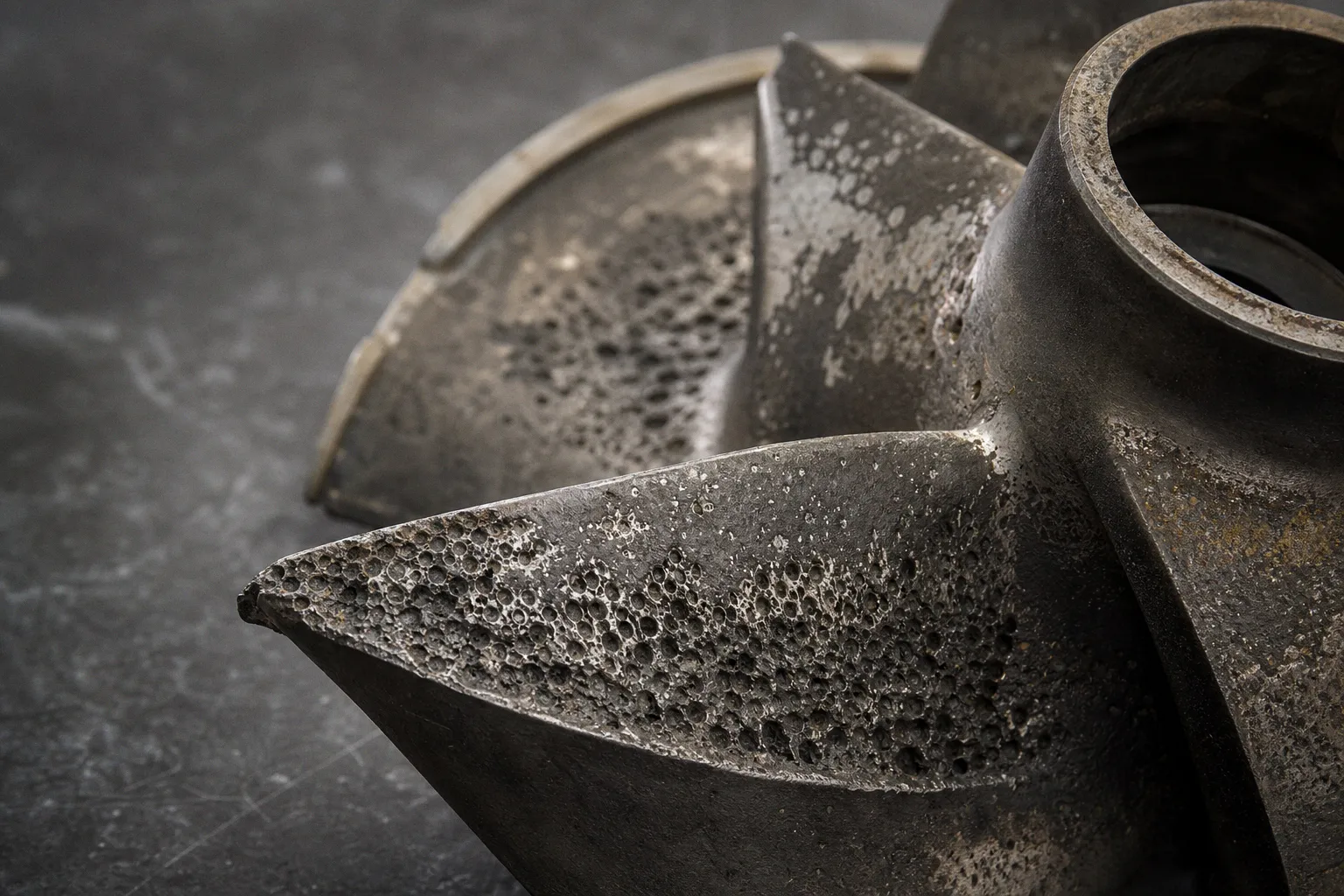
The liquid does not simply “boil” in the ordinary thermal sense. Vapor-filled cavities form in a low-pressure zone. As these bubbles move into regions of higher pressure inside the impeller passage, they collapse abruptly. Each collapse generates a local pressure shock. One event is small. Thousands of events per second are not.
The resulting damage pattern is predictable:
- Impeller vane surfaces develop pitting, typically near low-pressure regions and along the suction side of the vane.
- Repeated shock loading removes material and changes the hydraulic profile of the vane.
- Hydraulic efficiency declines before major geometry loss is obvious to the eye.
- Vibration transfers load into bearings, shafting, and mechanical seals.
- Seal face stability deteriorates when shaft movement and pressure fluctuations exceed the sealing system’s tolerance.
The visual evidence arrives late. By the time a vane looks as though it has been blasted with grit, throughput and service life have already been reduced.
Cavitation is not an impeller-surface defect. It is a pressure-management failure expressed on an impeller surface.
This is why preventing impeller damage from cavitation cannot be handled as a metallurgical problem alone. More resistant materials can delay erosion. They do not restore suction pressure, correct a restrictive suction line, or move the pump closer to its preferred operating region.
Noise is useful. Hydraulic evidence is better.
Cavitation often produces high-pitched crackling, rough running, or intense rattling as suction conditions deteriorate. These are valid warnings. They are also non-specific.
A damaged bearing, recirculation, pipe strain, misalignment, air ingestion, unstable control action, or debris can produce overlapping symptoms. Centrifugal pump noise troubleshooting fails when the maintenance workflow starts and ends with acoustics.
A lower-error-rate sequence uses multiple data streams.
1. Confirm the actual operating point.
Record flow, suction pressure, discharge pressure, liquid temperature, pump speed, and valve position under the condition where the symptom occurs. Compare the measured duty point with the pump curve, not with the original design duty. Installed systems drift. Control logic changes. Filters foul. Tank levels vary. A pump specified for one flow may spend most of its operating hours somewhere else.
2. Calculate available NPSH at the operating condition.
NPSHA is a property of the installed system. It changes with atmospheric pressure where applicable, vessel pressure, static liquid level, liquid temperature, suction-line losses, strainers, fittings, and fluid properties. It is not a nameplate value.
3. Compare NPSHA against the manufacturer’s NPSHR curve at the measured flow and speed.
NPSHR is a pump characteristic. It is not interchangeable with NPSHA. The difference is the NPSH margin. A valid comparison requires the same liquid basis, speed, and operating point used for the curve.
4. Trend head and efficiency rather than treating a single reading as proof.
Cavitation can reduce developed head and efficiency. A pump that still passes liquid may already be off its intended hydraulic condition. The process may mask this loss if a downstream control loop compensates by opening or closing valves.
5. Review vibration by trend and frequency content.
Cavitation-related vibration is often broadband and unstable rather than a clean signature at a single mechanical frequency. That does not make vibration analysis conclusive by itself. It makes it valuable when aligned with low suction margin, flow changes, and degraded head.
6. Inspect the suction path as a hydraulic component, not as plumbing.
Long runs, unnecessary elbows near the inlet, undersized pipe, loaded strainers, partially closed isolation valves, poor reducer orientation, vortexing in the supply vessel, and entrained gas all consume pressure margin or destabilize inlet flow.
The diagnostic objective is simple: reduce ambiguity before replacing hardware. A noisy pump with acceptable suction conditions and stable hydraulic output requires a different investigation from a noisy pump whose head falls as tank level drops and liquid temperature rises.
| Observed condition | Cavitation is plausible when | Alternative causes that remain possible |
|---|---|---|
| Crackling or rattling noise | Noise increases as suction pressure decreases or flow rises | Bearing damage, loose hardware, internal recirculation, solids |
| Increasing vibration | Trend tracks low NPSH margin or off-BEP flow | Misalignment, imbalance, pipe strain, bearing wear |
| Loss of head | Occurs near the high-flow end or under low tank level | Worn impeller, wrong rotation, discharge restriction, speed reduction |
| Seal leakage | Appears with pressure instability and vibration increase | Dry running, seal selection error, shaft runout, thermal distortion |
| Impeller pitting | Located in patterns consistent with low-pressure collapse zones | Corrosion, abrasion, chemical attack, solids erosion |
The table is not a substitution for testing. It is a routing mechanism. It prevents the common error of assigning every rough-running pump to cavitation and every cavitating pump to “bad bearings.”
NPSH3 is a test point, not a reliability promise
The term NPSHR is frequently used as though it describes the minimum suction head needed for normal operation. In most pump literature, the published value is NPSH3.
NPSH3 is the net positive suction head at which first-stage total head has dropped by 3% under a defined test condition. If a test head falls from 200 ft to 194 ft, the 3% criterion has been reached. The pump has not demonstrated cavitation-free behavior. It has demonstrated a measured performance loss associated with cavitation.
This matters because bubble formation, noise, vibration, erosion, and local flow instability can begin before the NPSH3 criterion is reached. The Hydraulic Institute guidance on NPSH margin addresses this gap. Its current ANSI/HI 9.6.1 guideline addresses NPSH margin, while ANSI/HI 9.6.3 addresses operating regions for rotodynamic pumps. Both are listed in 2024 editions.
The calculation structure is straightforward:
- NPSHA: pressure head available at the pump suction above liquid vapor-pressure head, after suction-side losses.
- NPSHR: pump demand at a specified flow, speed, and liquid condition, supplied by the manufacturer.
- NPSH margin: NPSHA minus NPSHR.
The engineering work is not straightforward because each term moves.
A tank level falls. Static head falls with it. A process liquid warms. Vapor pressure rises. A strainer loads with debris. Friction loss rises. A control decision increases flow. Pump NPSHR rises. The margin can collapse without any single component “failing.”
This is a system UX problem in the strict operational sense. The interface between process conditions, pump curve, instrumentation, and operator action has poor visibility. The operator sees noise. The pump sees a reduced pressure budget. The maintenance team sees pitting weeks later.
A generic fixed safety factor is not a valid design method. Margin requirements depend on pump geometry, fluid volatility, process consequences, operating range, manufacturer guidance, and the expected variation in the suction system. A vendor training example may use a specific allowance in a specific calculation. That does not make it a universal rule.
NPSHA equal to NPSH3 means the system has reached a 3% head-drop test condition. It does not mean the pump has a safe margin for service life.
For critical services—hot hydrocarbons, flashing liquids, chemical transfer, intermittent batch duty, low-level tank withdrawal—the selection package should make the margin visible across the operating envelope. One calculation at nominal flow and nominal temperature creates false confidence.
Flow rate changes cavitation risk even when the suction pipe does not
Cavitation is often assigned exclusively to the suction side. That is incomplete. The pump operating point matters.
Centrifugal pumps are designed around a best efficiency point, or BEP. Near BEP, inlet flow approaches the impeller at the intended angle and internal hydraulic losses are controlled. As the pump moves substantially away from BEP, incidence losses and flow separation increase. The inlet flow becomes less stable. Local pressure conditions deteriorate. Cavitation risk rises.
The Hydraulic Institute defines the preferred operating region as the area around BEP where efficiency and reliability are not substantially degraded. That definition should be read as a reliability constraint, not as a soft recommendation.
At excessive flow, the pump can experience:
- Higher velocity through suction piping and fittings, increasing friction losses.
- Increased NPSHR demand.
- Unfavorable inlet incidence at the impeller eye.
- Reduced head margin against system demands.
- Greater susceptibility to suction-side flow separation.
At very low flow, the failure mode differs but remains serious:
- Internal recirculation develops.
- Fluid can recirculate near the impeller inlet or discharge region.
- Localized heating and pressure fluctuations increase.
- Vibration and radial loading rise.
- Mechanical seal and bearing conditions can deteriorate even if the pump is not conventionally cavitating.
The pump may still produce the required process flow at either extreme. That is not a pass condition. Throughput alone is a weak metric. The stronger metric is stable throughput within the pump’s acceptable hydraulic operating region.
This is particularly relevant when oversized pumps are controlled through throttling. The control valve may maintain process flow, but the pump can be pushed toward a low-flow condition with poor internal hydraulics. Conversely, an underestimated system demand can drive a pump to the far right of its curve, consuming NPSH margin faster than the original design anticipated.
A pump selection review should therefore map at least four operating conditions:
1. Minimum expected flow.
2. Normal continuous flow.
3. Maximum expected flow.
4. The most demanding liquid-temperature and suction-level combination.
If the pump operates at variable speed, the map must include speed changes. NPSHR does not remain static when speed and flow move.
Correct the pressure budget before replacing the pump
The first corrective action depends on whether the system is short of available NPSH, the pump demand is too high at the duty point, or the pump is operating in an unstable region. These conditions can coexist.
Increase available suction head
Where the process allows it, increase the pressure available at the inlet:
- Raise the liquid level above the pump or relocate the pump to reduce suction lift.
- Increase source-vessel pressure where the process design permits.
- Reduce liquid temperature to lower vapor pressure.
- Increase suction-line diameter where friction loss is a dominant part of the deficit.
- Remove unnecessary fittings and short-radius elbows close to the inlet.
- Clean or resize strainers; treat differential pressure across a strainer as operating data, not a maintenance detail.
- Fully open suction isolation valves intended to be fully open.
- Correct inlet piping geometry so that flow enters the pump uniformly.
- Eliminate vortexing, air entrainment, and gas pockets in the suction path.
The cost hierarchy matters. Cleaning a blocked strainer or correcting a valve position has low implementation latency. Reworking a suction header or lowering a pump elevation has high capital cost and outage impact. Both can be correct. The root-cause data determines the order.
Reduce pump NPSHR by reducing flow or changing the hydraulic selection
If the immediate event is cavitation at excessive flow, reducing flow can reduce NPSHR. A discharge-side control valve can be throttled to move the pump left on its curve, provided the resulting flow remains adequate for pump cooling, lubrication, and minimum-flow requirements.
Do not throttle the suction side as a cavitation remedy. It adds suction loss and reduces NPSHA. That is the same failure mechanism, applied intentionally.
Discharge throttling is a stabilization measure, not always a final design. It may restore a workable operating point while the team resolves the underlying mismatch: wrong impeller diameter, excessive speed, inaccurate system curve, process expansion, or selection of a pump with insufficient suction capability.
Other design routes include:
- Select a pump with lower NPSHR at the required duty.
- Reduce rotational speed where the duty can still be achieved.
- Use a larger or differently configured pump operating nearer its BEP.
- Add a booster or modify the suction arrangement where process constraints prevent adequate static head.
- Reassess impeller trim and pump curve fit instead of treating flow throttling as permanent architecture.
For aggressive chemical services, this review must include seal materials and corrosion resistance, but those are secondary to the hydraulic cause. A chemically resistant impeller still cavitates if local pressure falls below vapor pressure.
Build a detection model that operators can use
A cavitation response procedure should not tell operators to “listen for unusual noise.” That instruction has low precision and high cognitive load. It leaves too much interpretation at the point of operation.
A better operating model ties symptoms to measurable state changes.
For a fixed-speed transfer pump, the alarm and review logic can be built around:
- Suction pressure trend relative to normal tank level and liquid temperature.
- Differential pressure across suction strainers.
- Actual flow against the pump’s preferred operating region.
- Discharge head or developed differential head against expected performance.
- Vibration trend, with baseline data collected when the pump is known to be stable.
- Motor load changes where they support the hydraulic diagnosis.
- Process conditions that alter vapor pressure, especially batch heating and solvent composition changes.
The system does not need every signal to identify every event. It needs enough correlated signals to reduce operator error rate.
For example, a rise in vibration alone should route a mechanical inspection. A vibration rise combined with falling suction pressure, increasing flow, and a drop in developed head should route an NPSH and operating-point review immediately. The difference is diagnostic latency. One path finds the cause during operation. The other waits for physical damage.
Instrumentation quality also matters. A pressure transmitter installed far from the pump inlet may miss local losses created by a strainer, valve, or fitting between the tap and the suction flange. Flow measurement with poor turndown or intermittent signal dropout creates false operating-point data. A trend screen that hides liquid temperature separates vapor-pressure risk from the display where it is needed.
This is not an argument for more dashboards. It is an argument for a smaller set of signals that align with the actual failure mechanism.
The practical decision is upstream of the impeller
Cavitation damage is often described as unavoidable wear in demanding service. That framing is convenient and usually wrong. Some services are difficult. Hot liquids, volatile media, changing tank levels, high flow variability, and constrained layouts create real limits. But most avoidable damage comes from treating NPSH as a catalog value and operating range as optional.
The pump does not distinguish between a design assumption and current plant conditions. It responds to actual inlet pressure, actual vapor pressure, actual flow, and actual internal flow pattern.
Use the following design heuristics:
- Calculate NPSHA at the worst credible combination of liquid level, temperature, pressure, and suction-line condition—not only at nominal duty.
- Treat published NPSH3 as a 3% head-drop criterion, not as proof of cavitation-free operation.
- Compare NPSHA and NPSHR at the measured operating point, including actual speed and flow.
- Keep continuous operation within the manufacturer-defined preferred operating region whenever process architecture permits.
- Diagnose cavitation through correlated hydraulic, vibration, and performance data; do not diagnose from noise or impeller pitting alone.
- Reduce excessive flow with discharge-side control when necessary; never create a suction restriction to solve a suction-pressure problem.
- Make suction strainer differential pressure, tank level, liquid temperature, and inlet pressure visible in the operating workflow.
- Replace damaged impellers only after the suction pressure budget and operating-point mismatch have been corrected.