Control valve cavitation traps causing hidden plant downtime
A control valve can be within its nominal flow range and still be the highest-risk wear point in a liquid pipeline. The failure mode is often not a leak or a visible actuator fault.
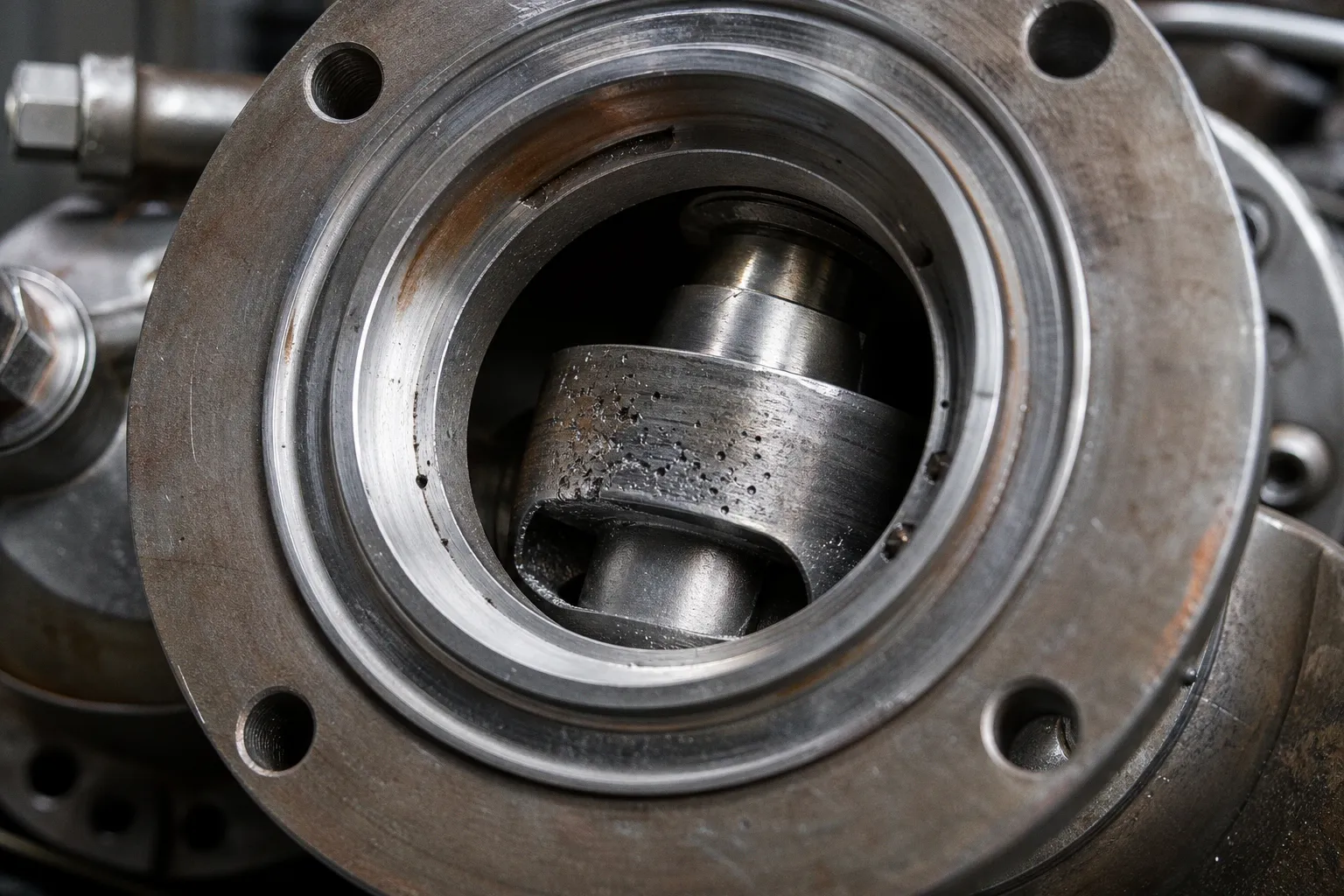
It is local pressure collapse inside the trim, followed by repeated vapor-bubble implosion downstream of the restriction.
This is control valve cavitation. Its cost is rarely visible in the original valve purchase order. It appears later as unstable control loops, roughened trim surfaces, vibration-induced failures in adjacent piping, unplanned maintenance windows, and throughput limits that operators learn to work around rather than formally diagnose.
The core error is simple: treating pressure drop as a sizing input only. In reality, pressure drop determines the energy released inside the valve. If that energy is dissipated in one aggressive restriction, the valve becomes a wear mechanism.
Cavitation is not a noise problem with a valve attached. It is an energy-dissipation problem with a maintenance bill attached.
Cavitation begins when local pressure crosses the vapor-pressure boundary
Cavitation occurs in liquid service only. As liquid accelerates through a valve restriction, static pressure falls. If local pressure falls near the liquid vapor pressure at the operating temperature, vapor bubbles form. When pressure recovers downstream, those bubbles collapse.
The collapse is the destructive phase.
Bubble implosion creates localized pressure pulses against the trim, valve body, downstream reducer, pipe wall, or other nearby components. Repetition changes smooth metal surfaces into pitted, rough, cinder-like profiles. That surface damage then worsens the hydraulic condition. Flow becomes less predictable. The valve’s effective characteristic shifts. Control-loop latency increases because the commanded position no longer maps cleanly to delivered flow.
At the system level, the sequence is usually:
1. A valve is selected for normal flow and nominal differential pressure.
2. A high pressure drop is concentrated across the valve at a low-load, start-up, or upset condition.
3. Local velocity rises through the restriction and local pressure falls toward vapor pressure.
4. Vapor bubbles form and collapse as downstream pressure recovers.
5. Trim geometry degrades, creating additional turbulence and variability.
6. Control performance declines before the component is visibly classified as failed.
7. Maintenance responds to vibration, leakage, noise, or poor throughput after damage has accumulated.
The last two stages create hidden plant downtime. The asset may remain online, but it consumes operator intervention, reduces usable operating range, and increases the probability that a short repair becomes a forced outage.
Liquid choked flow is the point where the problem becomes operational rather than theoretical. Once choking occurs, increasing pressure drop at constant inlet pressure no longer produces a corresponding increase in flow rate. The system absorbs additional pressure drop as velocity, turbulence, vapor formation, and mechanical stress rather than useful throughput.
This is why “more differential pressure” is not a control strategy.
The valve may be quiet while the trim is being damaged
Noise is useful evidence. It is not a reliable damage metric.
Intense cavitation can generate extremely high noise levels; guidance for control valves cites levels up to 115 dBA under severe conditions. That creates an obvious occupational and equipment concern. In U.S. general industry, an 8-hour time-weighted average of 85 dBA triggers hearing-conservation requirements, while 90 dBA is the permissible exposure limit.
Those limits matter for people. They do not define an acceptable cavitation condition for the valve.
A valve can produce substantial radiated noise without experiencing the worst material loss. The reverse is also true. Damaging cavitation can occur without audible noise, and measured noise or vibration does not necessarily track the quantity of damage occurring at the trim. The acoustic path between the valve and the measurement point introduces its own attenuation, reflections, insulation effects, and structural transmission variables.
That creates a common failure in maintenance workflow: a noise complaint receives attention, while a quiet but hydraulically severe valve remains below the intervention threshold.
Cavitation must also be separated from flashing. The distinction is not semantic. It determines the hardware strategy.
| Condition | Cavitation | Flashing |
|---|---|---|
| Fluid phase | Liquid forms vapor bubbles locally, then returns to liquid | Liquid forms vapor and remains partly vapor downstream |
| Downstream pressure | Recovers above vapor pressure | Remains below vapor pressure |
| Main destructive mechanism | Bubble collapse and localized impact loading | Persistent two-phase flow, high velocity, erosion, and flow instability |
| Typical location of damage | Trim, valve body, and recovery region downstream | Valve outlet and downstream pipework |
| Design objective | Prevent or reduce bubble formation and collapse | Manage continuous two-phase flow and erosion |
A cavitating valve is trying to recover pressure after the restriction. A flashing valve cannot recover enough pressure to collapse the vapor phase. Applying a cavitation solution to a flashing condition produces a poor result because the pressure-recovery assumption is wrong from the start.
Acoustic insulation can reduce external noise exposure. It can be necessary around a loud valve. But it does not stop vapor bubbles from forming or collapsing inside the valve and nearby piping. It treats the path, not the source.
A lower dBA reading outside the insulation enclosure does not mean a lower erosion rate inside the trim.
Hidden costs arrive first as degraded control performance
The most expensive cavitation damage is not necessarily a destroyed valve. A destroyed valve is visible. The expensive condition is progressive degradation that remains classified as “normal process variation.”
Three operational effects typically appear before a catastrophic mechanical failure.
Valve authority becomes less stable
As trim surfaces pit and passages roughen, the installed flow characteristic moves away from the selected characteristic. A linear trim does not remain functionally linear after repeated localized erosion. Equal-percentage behavior can also become distorted by damaged throttling edges and altered flow passages.
The control system sees this as inconsistent valve gain. A small movement at one position produces little response; the same movement elsewhere produces an oversized correction. The controller compensates with more activity. Stem travel increases. Actuator cycles increase. The loop may begin to oscillate.
This is not merely a tuning issue. Retuning a loop around damaged hydraulic geometry hides the root cause and increases cognitive load for operators.
Vibration spreads the failure boundary beyond the valve
The valve trim is not the only component exposed to cavitation energy. Structural vibration can reach:
- downstream pipe supports and guides;
- instrument impulse lines;
- pressure and temperature transmitter connections;
- welded branches and small-bore fittings;
- flange joints;
- actuator brackets and positioner hardware;
- reducers immediately downstream of the control valve.
A maintenance record may show repeated issues across these components without naming the valve as the common source. That is a classification problem. The asset hierarchy is organized by component type, while the failure mechanism crosses the entire local piping assembly.
Throughput is constrained by operator behavior
Operators learn where a valve becomes unstable. They avoid certain openings. They reduce differential pressure where possible. They hold a process below its nominal capacity because a higher rate creates noise, vibration, or poor response.
This is a throughput loss even when the valve has not failed. It may never appear as a discrete downtime event. It appears as a lower operating envelope, slower start-up, more manual intervention, and reduced confidence in automatic control.
The financial value of that loss cannot be assigned from a generic valve calculation. It depends on production margin, outage strategy, available bypass capacity, spare trim availability, and the process consequence of taking the loop offline. What can be measured directly is the operational pattern: increased controller output variance, repeat maintenance on downstream hardware, trim replacement intervals, and restricted valve travel bands.
Pressure-drop valve sizing is the primary control point
Control valve cavitation prevention starts with the pressure profile, not with a preferred valve body style.
There is no universal pressure-drop threshold, valve size, or cavitation index that makes every installation safe. The calculation depends on actual inlet pressure, outlet pressure, liquid vapor pressure at temperature, flow rate, fluid properties, valve recovery behavior, and the complete operating envelope.
That envelope must include more than the steady-state design point:
- normal minimum, normal, and maximum flow;
- minimum and maximum inlet pressure;
- expected downstream backpressure;
- liquid temperature and resulting vapor pressure;
- start-up conditions;
- shutdown and bypass conditions;
- upset cases that can concentrate differential pressure across one valve;
- future throughput cases if the line is expected to expand.
Start-up is routinely missed. A valve that is acceptable at full production may see its highest differential pressure when downstream equipment is empty, a downstream isolation valve remains partially closed, or the main process pump is operating against a low-flow path. That condition may be short in duration, but it can be repeated often enough to drive wear.
The sizing workflow should separate flow capacity from pressure-drop management. A valve can meet its required Cv and still be wrong for the service because it dissipates energy too aggressively in a single zone.
This is also where valve type selection becomes more disciplined. Globe valves, rotary valves, segmented ball valves, and specialized severe-service designs each have different recovery behavior, trim architectures, maintainability profiles, and installed footprint constraints. No single type is a universal cavitation solution. The correct choice follows a duty calculation and an operating-envelope review.
Multistage trim reduces the source, not just the symptom
The primary mitigation method for severe cavitation is source treatment: divide the total pressure drop into smaller stages.
A multistage pressure-drop trim routes the liquid through successive restrictions or channels. Each stage absorbs part of the total differential pressure. This reduces local velocity and aims to keep minimum pressure above the liquid vapor pressure, or at least reduce the severity and location of vapor formation.
The design objective is not simply “lower noise.” It is to reduce bubble generation and mechanical collapse energy.
A practical hierarchy of mitigation options looks like this:
1. Redistribute the system pressure drop.
If process design permits, avoid forcing a single control valve to absorb the full differential pressure. Separate restrictions, staged letdown arrangements, or changes in downstream pressure control can reduce concentration of energy.
2. Use multistage anti-cavitation trim where the duty requires it.
The number of stages, flow-path geometry, and materials must follow the actual sizing calculation. Selecting a multistage trim by reputation rather than duty point can create excessive pressure loss, poor controllability, or insufficient capacity.
3. Select a valve geometry with suitable pressure recovery.
Pressure recovery affects where and how rapidly pressure rises after the vena contracta. This changes cavitation behavior. It is a hydraulic selection variable, not a catalog preference.
4. Review downstream piping geometry.
Short reducers, abrupt expansions, tight elbows, and unsupported small-bore connections can become damage multipliers. The valve does not operate in isolation.
5. Apply acoustic path treatment only after source treatment is addressed.
Insulation, enclosures, and barriers can reduce radiated noise. They do not eliminate internal cavitation or vibration. Use them to manage exposure, not to certify hydraulic integrity.
The velocity relationship explains why incremental errors are expensive. Wear associated with cavitation corrosion can scale with velocity to a high exponent; one cited engineering reference places that exponent as high as 7, compared with roughly 2.5 for normal erosion mechanisms. The exact rate is service-specific. The directional implication is not: a modest rise in local velocity can produce a disproportionate increase in wear.
This is why an underspecified severe-service valve does not fail gradually in a convenient linear pattern.
Standards provide a calculation frame, not a substitute for operating data
IEC 60534-8-4:2015 provides a recognized method for predicting hydrodynamic noise generated by liquid flow in control valves, including noise associated with liquid cavitation. Its listed stability date is 2028.
The standard is useful because it forces a structured model of fluid conditions, valve behavior, and expected noise. It does not remove the need for field data. A prediction is only as credible as the inlet pressure, outlet pressure, temperature, vapor-pressure assumptions, valve coefficients, and operating cases provided to the calculation.
The same applies to vendor sizing outputs. A calculation generated from one nominal point has low value when the valve will experience wide changes in pressure ratio, temperature, or downstream backpressure.
A review that produces a robust result should document:
- the full set of normal, minimum, maximum, start-up, and upset cases;
- the governing cavitation and choking cases, not only the nominal case;
- expected valve travel at each operating point;
- predicted noise as an exposure and diagnostic input;
- trim architecture and pressure-drop distribution;
- downstream pipe configuration and vulnerable attachments;
- maintenance access and spare-trim lead time;
- the operational consequence if the valve must be bypassed or isolated.
This documentation reduces decision latency during commissioning and later failure analysis. Without it, teams reopen the hydraulic question only after hardware has already been damaged.
The operational model should treat cavitation as a leading indicator
Cavitation is usually discovered too late because plants classify it as a valve issue, a noise issue, or a vibration issue. It is all three, but the more useful classification is a flow-control integrity issue.
The field signals worth correlating are not limited to sound level. Look for changing valve position at a stable process load, rising controller output activity, repeat replacement of trim or downstream fittings, vibration concentrated around a throttling condition, unexplained drift in installed flow characteristic, and recurring operating restrictions during start-up.
A quiet valve can still be damaging itself. A loud valve may need worker-noise controls even if its trim remains serviceable. A successful mitigation plan separates those two decisions.
The design heuristics are direct:
- Model the full operating envelope before selecting the trim, with start-up and upset cases treated as design cases rather than exceptions.
- Separate required flow capacity from the ability to dissipate pressure drop without reaching destructive local conditions.
- Treat cavitation and flashing as different hydraulic states with different downstream damage patterns.
- Prefer source treatment through pressure-drop staging over acoustic treatment alone.
- Use noise predictions to manage exposure and support diagnosis, not as proof of valve integrity.
- Include downstream pipework, small-bore connections, supports, and instrumentation in the failure boundary.
- Track control-loop instability and repeat local maintenance as early indicators of cavitation damage.
- Do not accept a valve selection until the pressure-drop calculation, trim design, and installed piping constraints describe the same operating reality.