Check valve selection for high pressure liquid systems
A check valve can meet the line’s nominal size and headline pressure rating, then fail because it never reaches stable full-open travel. This is a common selection error in high-pressure liquid systems.
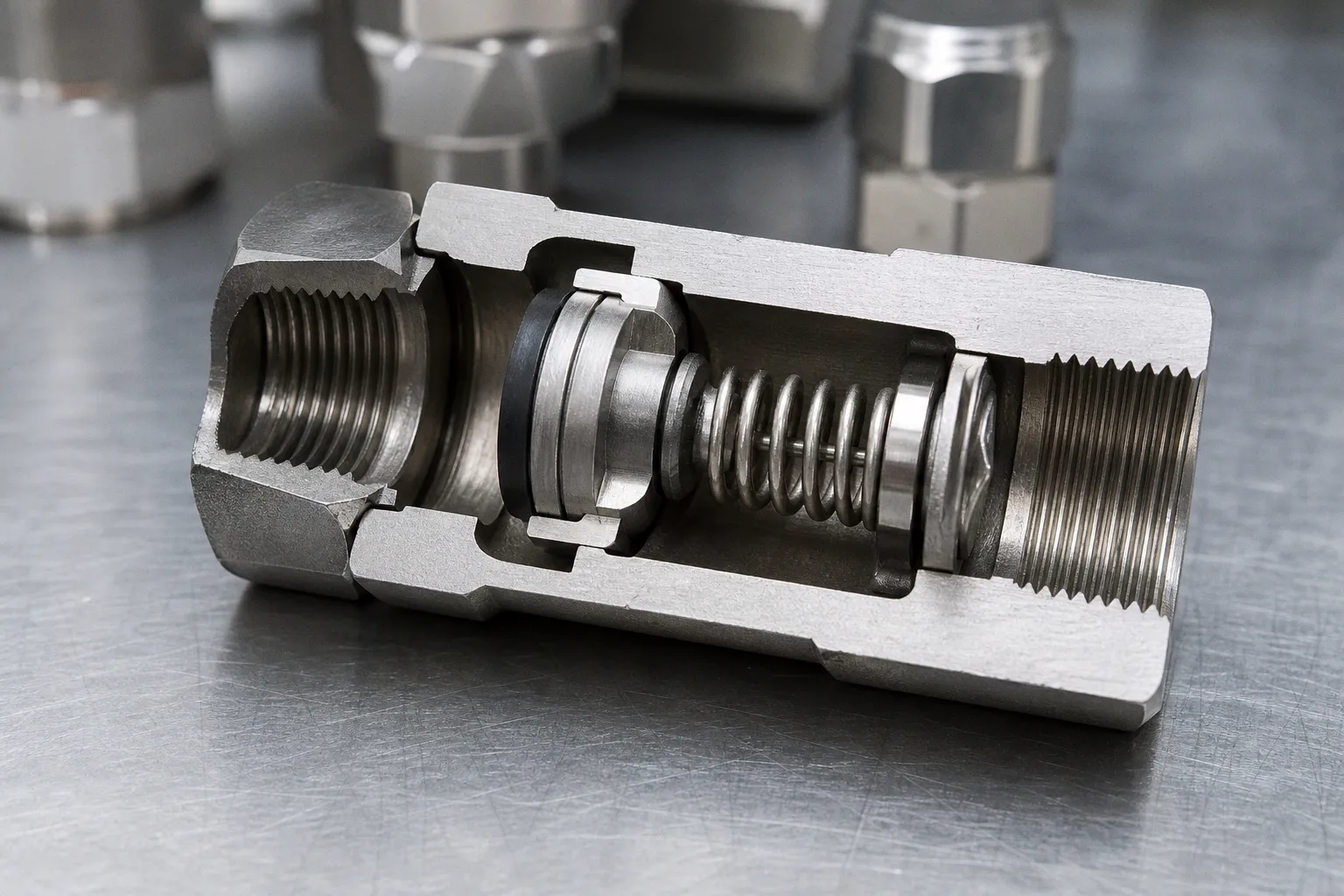
The immediate symptoms are chatter, seat wear, unstable downstream pressure, and premature reverse leakage. The root cause is usually not the valve body. It is a mismatch between available differential pressure, flow range, internal geometry, and transient behavior.
How to check check valve selection for high pressure liquid systems starts with the full operating envelope, not the pipe schedule. The valve must remain stable at minimum flow, limit pressure loss at maximum flow, reseal under the actual reverse differential, and survive the pressure-temperature and surge envelope of the installed system. These are separate constraints. A catalog pressure number does not combine them.
Beyond nominal pipe size: flow, Cv, and stable travel
Nominal pipe size is a connection decision. It is not a valve-sizing method.
A check valve with an oversized flow path can create a low differential pressure across the moving element. The poppet, disc, or ball may lift partially, oscillate in the flow stream, and impact the seat repeatedly. That raises the mechanical error rate of the system: the valve is technically passing flow, but it is not operating in a stable state.
An undersized valve produces the opposite failure mode. It may remain stable but add excessive pressure loss, reduce pump throughput, increase energy demand, or force operation closer to pump limits.
The working input is flow versus differential pressure across the valve. Cv is useful only when it is applied across the full range:
- Minimum continuous flow determines whether the internal element can lift and remain open without chatter.
- Normal operating flow determines the sustained pressure loss and the usual position of the closure element.
- Maximum flow determines whether the valve becomes a material restriction in the line.
- Available differential pressure determines whether a spring-loaded valve can overcome its spring force and hydraulic resistance.
- Fluid condition matters because viscosity, solids, gas entrainment, and temperature alter pressure loss and the response of moving internals.
For incompressible liquid service, engineers commonly use the relationship between flow, Cv, specific gravity, and pressure drop as an initial sizing screen. It is only an initial screen. It does not predict closure dynamics, disc flutter, or pressure surge. Those require the actual valve design curve and, for critical systems, transient analysis.
The selection sequence should be ordered. Reversing it creates avoidable rework.
1. Define the operating envelope before opening a catalog. Record minimum, normal, and maximum flow; fluid specific gravity; viscosity range; design temperature; normal upstream and downstream pressures; reverse-pressure condition; and pump operating modes.
2. Calculate the pressure differential available to open the valve. This is not line pressure. A system can operate at several thousand psi and still offer insufficient differential pressure across a generously sized check valve.
3. Compare the calculated range with the manufacturer’s flow and pressure-loss data for the exact valve series. Do not infer full-open behavior from the nominal cracking-pressure label.
4. Check stability at low flow. A valve that is stable only at peak throughput is not correctly selected for a process that spends most of its time at turndown.
5. Check maximum-flow loss. The selected Cv must not consume the pressure margin required by downstream equipment, control valves, injection points, or process restrictions.
6. Review the moving element and spring configuration. Poppet, piston, ball, dual-plate, and swing mechanisms have different closure behavior. The right geometry depends on velocity, orientation, cleanability, and reverse-flow dynamics.
Pipe size defines the envelope. Differential pressure defines whether the check valve actually works inside it.
The key constraint is internal stability. A valve that cycles between partly open and partly closed adds latency to the flow path and mechanical wear to the sealing path. Neither is visible in a nominal-size comparison table.
Cracking pressure is not full-open pressure
Cracking pressure is frequently treated as a complete performance specification. It is not.
Cracking pressure is the upstream differential at which detectable forward flow begins. It says that the closure element has started to move. It does not establish the pressure needed to drive the element fully open. It does not establish the pressure at which the valve will reseal. It does not establish a leakage rate under reverse pressure.
These states need to be separated.
| Valve state | What it means | Selection consequence |
|---|---|---|
| Cracking | Forward differential first produces measurable flow | Sets the initial opening threshold |
| Full open | Internal element reaches stable travel with low restriction | Determines chatter risk and sustained pressure loss |
| Reseal | Reverse differential returns the closure element to the seat | Determines isolation behavior after flow reversal |
| Leak-tight sealing | Reverse pressure and seat design meet the stated leakage criterion | Must match the actual reverse-pressure condition and test basis |
Product data illustrates the gap. In one Parker C-series spring example, a nominal 25 psig cracking setting has an acceptable actual cracking range of 20 to 30 psig, or 1.38 to 2.07 bar. The stated reseal range is 16 to 20 psig, or 1.10 to 1.38 bar. These are distinct bands. Treating “25 psi cracking” as a precise opening and closing threshold is an input error.
Tolerance matters in two directions. If the actual cracking threshold is at the high end of tolerance, minimum-flow operation may not open the valve sufficiently. If it is at the low end, the valve may open earlier than the process logic assumed. The effect becomes more pronounced when several check valves operate in parallel paths or when the valve protects a low-margin pump discharge.
Low cracking pressure does not automatically mean low reverse sealing pressure. Some low-cracking designs may require reverse-side pressure to obtain bubble-tight resealing. Parker states that models rated at 3 psig cracking pressure or below may require up to 4 psig, 0.28 bar, of back pressure for bubble-tight resealing. Its PTFE-seated check valves have a much higher stated requirement: at least 100 psig, 6.9 bar, of back pressure for leak-tight resealing.
That is not a universal PTFE rule. It is a product-specific requirement. The design implication is broader: a seat material and valve architecture can change reverse-sealing behavior materially.
The required review is therefore more specific than “select the correct spring.” It should answer the following:
- What is the lowest forward differential at minimum stable flow?
- Is that differential enough to move the closure element beyond the unstable partial-travel zone?
- What reverse differential exists during normal shutdown, pump coastdown, and maintenance isolation?
- At what reverse pressure does the exact valve configuration meet its stated leakage criterion?
- Does the process permit the manufacturer’s defined leakage level, or is a separate isolation function required?
A check valve is a directional flow-control component. It should not be assigned the task of positive isolation unless the manufacturer data and system design support that function.
The pressure rating is a configuration, not a headline number
High-pressure selection often fails at the configuration boundary. The body material appears adequate. The selected seat, end connection, or temperature condition reduces the usable limit.
Pressure-temperature ratings must be checked for the exact body, seat, seal, size, and end-connection combination. A stainless-steel valve body does not carry one fixed rating across all internal configurations.
The Parker C-series provides a clear example of this logic. In that product family, 316 stainless-steel models in 1/8 through 3/4 inch sizes are listed at 6,000 psig, 414 bar, cold working pressure. The 1-inch size is listed at 5,000 psig, 345 bar. PTFE-seat versions are limited to 4,000 psig, 276 bar, across sizes. Brass versions are listed at 3,000 psig, 207 bar.
The hierarchy is direct:
1. Body size changes the rating.
2. Seat construction changes the rating.
3. Temperature changes the usable pressure-temperature envelope.
4. End connection and applicable piping code can add further limits.
A procurement description that reads “1/2-inch stainless check valve, 6,000 psi” has high cognitive load and low engineering value. It omits the variables that control suitability.
Seat and elastomer limits require the same discipline. In the cited product data, fluorocarbon rubber and PTFE are listed from -15°F to 400°F, -26°C to 204°C. Nitrile is listed from -30°F to 275°F, -34°C to 135°C. Ethylene-propylene rubber is listed from -70°F to 275°F, -57°C to 135°C. These are manufacturer-specific limits for that series. They should not be copied into another vendor’s specification.
Material review has two layers.
Chemical compatibility
The wetted material must tolerate the liquid, including additives, cleaning fluids, contamination, and periods of stagnant exposure. A valve may see a different chemical profile during flushing than during production. Seat swelling, hardening, extraction, and loss of lubricity are all relevant failure mechanisms.
Mechanical compatibility
The material stack must retain sealing and structural performance at the combined pressure-temperature condition. High pressure amplifies small losses of seat support, extrusion resistance, and dimensional stability. The result may be external leakage, internal reverse leakage, or a shift in cracking behavior.
ASME B16.34-2025 provides the relevant framework for flanged, threaded, and welding-end valves, including pressure-temperature ratings, materials, dimensions, tolerances, examination, testing, and marking. It does not remove the need to check the exact manufacturer configuration or the governing piping and pressure-equipment code.
A 6,000-psi body is not a 6,000-psi valve until the seat, temperature, connections, and service condition are attached to the statement.
Surge risk changes the selection problem
Steady-state calculations are necessary. They are not sufficient.
High-pressure liquid systems can generate damaging transient loads when pump velocity changes quickly. Pump shutdown, rapid pump trip, power loss, abrupt control-valve movement, and check-valve closure can initiate surge. In severe cases, liquid-column separation occurs. When the separated columns rejoin, the resulting shockwave can exceed the steady operating pressure by a large margin.
The error rate here is organizational. A valve is selected from steady flow data, then the system is expected to absorb an event that was never modeled.
Check-valve closure speed matters, but “fast closing” is not a standalone solution. A fast-closing design may reduce reverse flow and limit the mass of liquid moving backward before closure. It can also create a sharper pressure event if the surrounding system cannot absorb the deceleration. A slower mechanism can allow greater reverse velocity before seating. Neither description establishes suitability without the pipe profile, fluid properties, pump coastdown curve, and valve dynamics.
The transient review should include:
- Pipe material, length, diameter, and elevation profile.
- Liquid properties at operating temperature.
- Normal velocity and flow range.
- Pump curve, rotating inertia, and coastdown behavior.
- Pump trip and restart scenarios.
- Valve location relative to the pump, header, high points, and control valves.
- Expected closure dynamics of the selected check valve.
- Existing surge-control devices, relief capacity, accumulators, air vessels, or controlled pump shutdown logic.
A check valve cannot substitute for a surge study where the consequence of pressure excursion is material. It is one component in the transient-response chain.
For a compact local line, the consequence may be limited to noise, seat damage, and shortened service life. For a long high-pressure liquid line, the same selection error can propagate into pipe supports, flanges, pump connections, instrumentation taps, and adjacent valves. The system throughput may return after the event. The accumulated fatigue damage remains.
Installation geometry controls flow quality
A properly selected valve can still receive poor inlet conditions.
Turbulence and swirl cause unstable movement of the internal closure element. This is particularly relevant downstream of pumps, tees, reducers, increasers, and elbows. The valve sees a distorted velocity profile rather than the stable flow assumed by its bench data.
Reported MSS SP-92 guidance calls for at least 10 pipe diameters downstream of tees, fittings, increasers, or pumps, and five pipe diameters from elbows. These distances are a practical starting point, not a universal substitute for manufacturer review. Space-constrained layouts should be evaluated with the valve supplier using the actual orientation and flow conditions.
Installation review should also cover orientation. Some designs are tolerant of multiple orientations. Others depend on gravity, spring force, or a specific vertical-flow direction. A drawing note such as “install per arrow” is insufficient for a valve where disc mass and gravity affect closure timing.
The practical installation variables are:
- Flow direction and physical orientation.
- Straight-run availability upstream and downstream.
- Proximity to a pump discharge.
- Reducers, expanders, and elbows near the valve.
- Accessibility for inspection or replacement.
- Support design so that pipe loads do not distort the valve or its end connections.
- Drainage and venting behavior, especially where trapped liquid or gas can affect resealing.
- Instrument locations used to diagnose pressure drop, cycling, or reverse-flow events.
API Std. 594 is the relevant API standard family for check valves with flanged, lug, wafer, and butt-welding end configurations. The 8th edition was published in 2017. A committee ballot for a 10th edition passed on May 1, 2026, but a passed ballot alone should not be treated as confirmation that the edition has been formally published. Use the edition contractually required by the project specification and verify the current publication status before citing it.
A selection record that can survive review
The output of check-valve selection should be a short engineering record, not a part number with a pressure rating attached. The record should allow another engineer, operator, or maintenance lead to reconstruct the decision without reopening the entire process model.
At minimum, document the actual valve configuration, pressure-temperature rating, seat and seal materials, end connections, forward flow range, estimated pressure loss, cracking tolerance, reseal requirement, reverse-pressure condition, orientation, installation geometry, and transient-analysis disposition.
This reduces latency during commissioning and failure analysis. It also exposes missing inputs early. If the system team cannot state the minimum differential pressure, reverse reseal condition, or pump-trip behavior, the selection is incomplete regardless of how detailed the catalog page appears.
The operating principle is simple. Stable forward operation, controlled reverse closure, and adequate structural margin must all exist in the same configuration. A check valve that satisfies only one of those states is not a finished design.
Use these design heuristics:
- Select against the full flow and differential-pressure envelope, not nominal pipe diameter.
- Keep cracking pressure, full-open behavior, and reseal pressure as separate requirements.
- Treat Cv as a stability and pressure-loss variable, not a catalog sorting field.
- Verify body, seat, seal, size, end connection, and temperature as one pressure-rated configuration.
- Do not claim leak-tight reverse isolation until the valve’s stated reseal condition and leakage criterion match the system.
- Run a transient review for pump shutdown and other rapid velocity changes before assigning surge protection to the check valve.
- Preserve straight-run geometry where possible; escalate constrained layouts to the valve manufacturer.
- Record the selection assumptions. Unrecorded assumptions become field failures.