Industrial gate valves versus globe valves: mapping flow control paths
By the middle of a shift, an operator usually does not need a textbook to tell the difference between a valve that belongs in an isolation duty and one that belongs in a control loop.
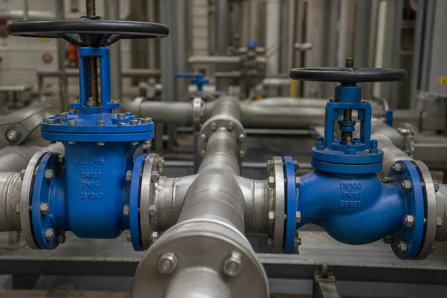
They feel it in the handwheel: the gate valve that is either confidently open or firmly shut, and the globe valve that asks for small, deliberate adjustments while the downstream pressure settles. The trouble begins when those roles get blurred on a P&ID, in procurement, or during a quick field replacement.
Compare car rental deals in United Kingdom
See available offersPartner link — DiscoverCars comparisonIndustrial gate valve versus globe valve selection paths start with a plain question: are we trying to clear the pipeline for flow, or shape the flow while the process is running? Both valves can stop a line. Both may be found in heavy-duty steel construction across serious pressure classes. But their internal geometry gives them very different jobs, different losses, and different failure modes when we ask them to do work they were not designed to do.
On the ground, this is not a semantic distinction. It affects pump energy, steam stability, valve wear, operator fatigue, actuator selection, and whether a line behaves predictably after someone turns the handwheel two more times than planned.
The flow path tells us what the valve wants to be
A gate valve is built around a moving gate, wedge, or parallel obturator that travels out of the fluid stream as the valve opens. When it reaches full open position, the bore is close to a straight-through passage. The flowing medium does not need to make a sharp internal turn simply to pass the seat.
That uncomplicated path is the reason gate valves are such familiar pipeline isolation valve choices. In a large water line, a refinery transfer line, or a long utility header, the fully open gate valve contributes relatively little resistance compared with a valve whose internals force the fluid to change direction. It is there to establish one of two clean states:
- Open: the line is available with minimal obstruction from the valve.
- Closed: the gate contacts the seats and isolates the downstream section.
- In between: a temporary mechanical position, not a reliable flow-control setting.
A globe valve works differently. Its body and seat arrangement direct fluid through a more tortuous route, typically across the seat area and around a plug or disc. Instead of lifting a closure element entirely out of the main stream, the valve varies the opening through which fluid must pass. That creates a much more usable relationship between stem movement and flow restriction.
This is why globe valve flow control options are so much broader. You can use the valve for shutoff, certainly, but its real advantage appears when you need to trim a flow, manage a pressure reduction, or work with an actuator and positioner in a control loop. The design accepts that it will impose resistance because that resistance is part of how it does its job.
| Operating question | Gate valve | Globe valve |
|---|---|---|
| What is the primary duty? | Isolation: start or stop flow | Regulation plus positive shutoff |
| What happens to the flow path when fully open? | Near-straight path with low resistance | Direction changes inside the body |
| Is intermediate travel a normal operating condition? | No; it is generally unsuitable for throttling | Yes; controlled intermediate positions are central to the design |
| Typical consequence in a flowing line | Lower pressure loss when fully open | Higher pressure loss, but more controllable restriction |
| What does the operator need most? | Clear open/closed indication and dependable seating | Repeatable adjustment, usable tactile feedback, and stable response |
We can think of it as a doorway versus a hand-controlled nozzle. If you need to open a route completely or seal it off, a doorway is useful. If you need to meter what comes through, the nozzle gives you a usable range of positions. Trying to meter a process through a partly raised gate is like trying to regulate a water hose by leaving a heavy door half across its opening: it may alter the flow, but it is not a stable or graceful way to do it.
A low-resistance path is not a control characteristic. It is the reward you get when an isolation valve is allowed to be fully open.
Gate valve application paths: where straight-through flow earns its place
A gate valve makes sense where pressure loss in normal operation should remain low and where the process does not ask the valve to continuously balance the flow. Common examples include main isolation points on long pipelines, upstream and downstream block valves around equipment, and sections of a network that must be isolated for maintenance.
If the maintenance team needs to pull a strainer, replace a pump seal, or isolate a branch for inspection, then the useful question is not “How finely can we adjust this line?” It is “Can we positively separate this section from the system and restore full capacity when the job is done?” That is a gate-valve question.
The same clarity matters in control-room logic and maintenance procedures. An actuator on a gate valve can automate open-and-close isolation, but automation does not transform the valve into a modulating device. If the duty requires repeated positioning at partial travel, we need to step back before selecting the actuator and examine the valve geometry itself.
Globe valve flow control options: where restriction is intentional
Globe valves earn their pressure drop by making flow adjustment practical. In services where an operator or control system needs to make small changes and see a repeatable response downstream, the disc-and-seat arrangement offers a more appropriate mechanical conversation with the process.
That conversation becomes especially important in steam and thermal utility work. A steam control valve needs enough useful pressure differential across it to regulate in a stable way. Guidance for steam control-valve sizing warns that, at full load, a pressure drop below 10% across the valve can contribute to unstable control, poor low-load behavior, and wiredrawing risk. That is not a universal rule for every globe valve or every fluid; it is a reminder that control authority must be designed into a steam application rather than assumed from the valve label.
If the pressure drop available to the control valve is too small, then a small stem movement may not produce a controllable process change. The operator turns the handwheel or the positioner hunts for an answer, but the system gives almost no useful tactile feedback or process feedback until it suddenly gives too much. This is one of those moments where hardware UX is not a soft layer applied after engineering. The geometry, pressure balance, trim, actuator thrust, and feedback loop are the user experience.
Pressure drop is not an inconvenience; it is part of the assignment
It is tempting to describe pressure drop as simply good or bad. In real-world context, it is neither. It is a cost when the valve is supposed to disappear from the flow path, and it is a working tool when the valve is supposed to regulate energy and capacity.
In a comparable fully open water service, a gate valve normally produces less pressure drop than a globe valve. The globe valve’s internal directional change and seat arrangement create a larger head loss and, all else equal, a lower available flow rate. That is not a defect in the globe design. It is the mechanical basis for its ability to control.
The selection sequence should therefore move in this order:
1. Name the process action before naming the valve.
If the line must be isolated for a pump changeout, a branch shutdown, or emergency segregation, begin with an isolation-duty valve. If the process needs a controlled rate, temperature response, pressure reduction, or steam balance, begin with a control-duty valve.
2. Map the required valve positions.
If the valve will spend almost all of its life either fully open or fully closed, a gate valve may be appropriate. If it will routinely live at 20%, 45%, or 70% travel, that is a clear signal to consider a globe valve or another purpose-built control valve.
3. Calculate the available pressure drop in the actual system.
Pipe length, elevation, pump curve, fluid density, temperature, downstream pressure, and fouling margin all shape the result. We should not use a generic gate-versus-globe loss ratio because body geometry, nominal size, trim, and opening position change the outcome substantially.
4. Look at the medium, not only the line size.
Clean water, saturated steam, flashing liquid, slurry, corrosive process media, and high-temperature hydrocarbon service ask different things of seats, trim, body materials, and pressure recovery. A globe valve is not automatically the right answer just because control is needed; ball, butterfly, rotary plug, or multi-stage control designs may be more appropriate for a specific duty.
5. Design for the person who must operate and maintain it.
A large handwheel that requires many turns, an inaccessible rising stem, a valve installed against its specified flow direction, or an actuator with poor position feedback can create operator fatigue and routine workarounds. Those workarounds eventually become reliability problems.
This is why industrial valve selection criteria should be read as a path through the system rather than a row of isolated catalog fields. Pressure class matters. End connection matters. Seat and body material matter. But none of them can correct a mismatch between the valve’s flow path and the operating behavior demanded by the process.
The hidden cost of throttling with a gate valve
Everyone who has spent time around a live plant has seen the practical temptation. The installed gate valve is already there. The line is flowing too hard. Someone needs a smaller flow now, not after the next shutdown. So the handwheel is backed off from full open and the partially closed gate becomes a makeshift restriction.
It can look harmless from the outside. The line flow falls. The gauge responds. The job seems solved.
Inside the valve, the story may be much less comfortable. A gate valve used for throttling can experience disc chatter and flow fluctuations. The partially exposed gate sits in a high-velocity, uneven flow field that it was not intended to manage as a steady operating state. Repeated turbulence and vibration can damage seating surfaces and create a valve position that is neither dependable isolation nor dependable control.
If the process is sensitive, the result is not merely valve wear. A fluctuating restriction can pass instability downstream: pump cycling, uneven filling, temperature swings, variable spray patterns, or a control loop that continually compensates for a mechanical behavior it cannot see clearly.
Motor-operated throttling is an especially poor fit. Technical design criteria from the U.S. Department of Energy explicitly state that gate valves must not be used for motor-operated throttling service. Where manual throttling is needed, the guidance points toward a globe valve with a guided disc or plug, or toward a ball valve depending on the service.
The “depending on the service” portion matters. We should resist replacing one shortcut with another. A globe valve is a strong candidate for throttling, but pressure drop, capacity, solids, noise, cavitation, erosion, and rangeability can all alter the right answer.
If-then decisions that prevent a bad substitution
Here is the practical route we can use during design review or a field modification discussion:
- If the line needs full-bore availability during normal production and only occasional shutdown isolation, then select a gate valve path and keep the valve fully open in service.
- If the operator must regularly dial in flow while watching a downstream pressure, temperature, or level response, then select a globe valve or another dedicated control-valve path sized for that control duty.
- If the process medium carries solids or the line has conditions that make a conventional globe trim vulnerable to erosion or plugging, then do not force the globe selection; review rotary or specialized control-valve options with the process data in hand.
- If the valve will be automated, then confirm whether the actuator is being asked to do isolation or modulation. An actuator’s presence is not evidence that the underlying valve is suitable for modulating duty.
- If a field team says the gate valve is “working fine” half open, then ask how long it has been in that position, whether there is audible vibration, whether the flow is stable, and whether the valve must later provide tight shutoff. Those answers often reveal the deferred problem.
The quickest way to create a maintenance problem is to call a temporary restriction setting a control strategy.
Body pattern, trim, and flow direction still need a drawing-level review
It is useful to speak in broad categories—gate for isolation, globe for control—but the final valve selection happens at a more detailed level. A globe valve can come in conventional, Y-pattern, and right-angle configurations. Those patterns change piping layout, available pressure drop, maintenance access, and the way the valve integrates with an existing skid or pipe rack.
A right-angle globe valve, for example, can combine a directional change with a shutoff/control point where the piping itself turns. A Y-pattern arrangement may offer a different balance of flow path and accessibility than a conventional globe body. The correct form depends on the required duty, layout, pressure-temperature envelope, trim, and actuator arrangement.
Flow direction deserves the same care. There is no universal rule that every globe valve must be installed in one direction, and we should not assume that every gate valve behaves identically in either direction. The body arrow, manufacturer documentation, specified trim, pressure differential, and actuator requirements govern the installation. This becomes more consequential when there are high differential pressures, noise limits, cavitation concerns, or unbalanced forces acting on the closure element.
From the operator’s perspective, good installation practice produces a valve that behaves as expected. The opening direction is clear. The handwheel or actuator remains accessible. The stem travel can be inspected. The valve can be isolated and serviced without turning a small access platform into a test of balance and patience. These details can sound ordinary in a design meeting, but on the ground they determine whether the hardware supports careful work or encourages rushed work.
Standards tell us what was built, not what process decision to make
In refinery and related heavy-duty applications, standards provide an important common language for construction and testing. But a standard number should never be used as a shortcut around process selection.
API 600 addresses heavy-duty bolted-bonnet steel gate valves for refinery and related use, including flanged and butt-welding ends. Its stated scope covers nominal sizes from NPS 1 through NPS 42 and pressure classes from Class 150 through Class 2500.
API 623 addresses heavy-duty bolted-bonnet steel globe valves for refinery and related applications. Its first edition covers globe-valve configurations including conventional, Y-pattern, and right-angle bodies, for NPS 2 through NPS 24 and the same Class 150 through Class 2500 range.
ISO 6002:2021 applies to bolted-bonnet steel gate valves with single or double obturators, wedge or parallel seating, and flanged or butt-welding ends. Its scope reaches DN 10 to DN 1,000, corresponding to NPS 3/8 through NPS 40, and the edition remains current following ISO’s 2026 review.
These references are valuable when we need to align procurement, fabrication, inspection, and documentation. They help establish what kind of product is being specified. They do not certify that a particular valve will handle a particular fluid, pressure drop, temperature cycle, corrosion mechanism, or control objective.
Before releasing a purchase order, the design team still needs to resolve:
- the pressure-temperature rating for the actual material and service;
- end connections and piping class;
- packing and fugitive-emissions requirements where applicable;
- seat, disc, plug, and trim materials;
- required shutoff performance;
- calculated capacity and pressure drop;
- noise, cavitation, flashing, or erosion exposure;
- manual versus pneumatic or electric actuation;
- maintenance clearance, orientation, and access for the people who will work the valve.
That last line belongs in the technical specification, not in a separate “nice to have” conversation. A valve may satisfy every paper requirement and still be a poor piece of installed hardware if its operation demands unsafe reach, excessive force, or blind troubleshooting.
A better valve map begins with the work, not the catalog
There is a straightforward reason gate and globe valves continue to coexist in industrial systems: they solve different parts of the same flow problem.
Use the gate valve where the system needs an open highway or a positive barrier. Its low-resistance, straight-through character is valuable precisely because we do not ask it to perform fine regulation. Use the globe valve where controlled restriction and repeatable adjustment are part of normal operation, accepting that the internal flow path carries a pressure-drop cost.
When we make that distinction early, the rest of the design becomes easier to defend. The pipe sizing is more honest. The actuator specification is more coherent. The control loop has a real chance of being stable. And the person standing beside the valve at 2 a.m. is not being asked to translate a compromise into a workable operating procedure.
That is the most useful outcome of industrial valve selection: not simply a correct item in a bill of materials, but hardware that lets the people running the plant understand what the line will do when they open it, close it, or make a careful adjustment in between.