Pneumatic or electric actuators for industrial valves
A valve can be perfectly specified on paper and still become the point where a shift slows down. The operator presses a command, watches the indicator, waits for a damper to move or a line to isolate—and nothing happens at the pace the process needs.
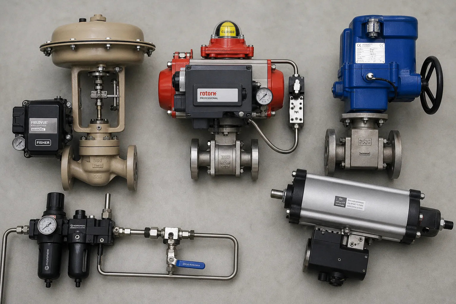
Sometimes the actuator is undersized. Sometimes the air supply is wet. Sometimes an electric unit was selected for a modulating duty it was never meant to carry. More often, the problem began earlier: someone treated “pneumatic or electric?” as a catalogue choice instead of a whole-system decision.
Compare car rental deals in United Kingdom
See available offersPartner link — DiscoverCars comparisonThat is the practical center of any pneumatic vs electric valve actuators comparison. We are not choosing between two motors in different housings. We are choosing a power source, a response pattern, a maintenance burden, a fail position, and, ultimately, the amount of confidence an operator has when a valve must move right now.
On the ground, the best choice is rarely the actuator with the most impressive headline specification. It is the one that fits the actual valve torque or thrust, the available utilities, the speed of the process, the duty profile, and the consequences of losing power or air.
Two power sources, two very different operating environments
Pneumatic actuators convert compressed-air energy into mechanical movement. Depending on the assembly, that movement can be rotary for a ball valve, butterfly valve, or plug valve, or linear for a globe valve and other linear-stroke designs. The familiar quarter-turn pneumatic package is often a rack-and-pinion or scotch-yoke actuator paired with a solenoid valve, air preparation equipment, and possibly a positioner.
Electric actuators convert electrical current into mechanical energy through a motor, gearing, and control electronics. They can also deliver rotary or linear movement, but the package carries more of its intelligence locally: torque sensing, position indication, local controls, interlocks, and communication interfaces are commonly integrated into the actuator enclosure.
That distinction matters because the actuator never works alone.
If a site already has stable, dry instrument air distributed close to the valve bank, pneumatic automation can be physically straightforward. The valve gets a compact mechanical drive; the control system sends a signal to a solenoid or positioner; the air does the work. If the site has limited compressed-air capacity, long air runs, or expensive compressor operation, the same “simple” pneumatic package becomes less simple very quickly.
If power and network wiring are already present at remote valve locations, electric actuation can remove the need for air tubing, filter-regulator assemblies, and local air infrastructure. But then we need to look honestly at enclosure suitability, cable routing, voltage stability, actuator heat, and how the unit behaves when power disappears.
The actuator is not a bolt-on accessory. It is the part of the valve system that turns a control-room instruction into a physical event.
For a person walking the line, this difference is felt in small but consequential ways. An air leak may announce itself with a persistent hiss and gradually reduce performance. An electric actuator may look quiet and tidy until a duty-cycle mismatch or torque trip puts the valve out of service. Neither failure mode is inherently better. They simply ask different things of the maintenance team and the plant infrastructure.
Torque, thrust, and speed: where selection becomes real
Valve size is a poor shortcut for actuator selection. Two 8-inch ball valves can demand very different breakaway torque because of seat material, pressure differential, media properties, cycling history, temperature, and how the valve has been sitting in service. A linear valve brings a different set of loads: stem thrust, packing friction, unbalance forces, seating force, and the required control behavior near the seat.
We need the valve manufacturer’s operating data—or a defensible calculation—for at least these conditions:
- Breakaway torque or thrust, the force required to start a valve that has been static under process conditions.
- Running torque or thrust, the demand while the closure member is moving through its stroke.
- Seating and unseating demand, often the decisive load for shutoff performance and the first movement after prolonged closure.
- Pressure differential and media effects, because clean water, slurry, steam, viscous product, and dry gas do not load the valve in the same way.
- Required stroke time, including whether a rapid movement creates hydraulic shock, pressure upset, or a safety benefit.
- A realistic margin, selected for the valve and service rather than copied as a blanket percentage from an old project template.
Pneumatic actuators are often appreciated for their direct, high-force response. With adequate air volume, pressure, valve sizing, and correctly selected tubing and solenoid capacity, they can move quarter-turn valves quickly. That does not mean every pneumatic actuator is automatically fast. A small air line, restrictive fittings, a poorly sized solenoid, or a long run from the receiver can turn a brisk package into a sluggish one.
Electric actuators generally create motion through a motor and reduction gearing. That gearing can produce substantial output torque, but it also shapes speed. A high-torque electric actuator may move a large valve deliberately rather than instantly, and that can be exactly right for a process vulnerable to surge or water hammer. The mistake is assuming that “electric” means slow, or that “pneumatic” means fast, without looking at the demanded travel time and the full assembly.
| Selection question | Pneumatic actuator | Electric actuator |
|---|---|---|
| Where does the energy come from? | Compressed-air network, local receiver, or dedicated air source | Electrical supply at the valve location |
| Typical motion character | Direct mechanical response shaped by air pressure, flow capacity, and actuator geometry | Motor-and-gear motion shaped by motor rating, gearing, control settings, and torque limits |
| What often limits real response time? | Air line diameter, fitting losses, solenoid flow, available air volume, and exhaust path | Motor speed, gear ratio, torque demand, electrical supply, and configured travel limits |
| What must be calculated first? | Valve torque/thrust across the stroke and available air pressure under demand | Valve torque/thrust across the stroke and available motor torque at the required duty |
| What does the operator notice? | Audible exhaust, visible tubing, often intuitive local troubleshooting | Quiet operation, local display or indicators, more information available at the actuator |
| What can quietly undermine performance? | Contamination, water, oil, pressure drop, leaking tubing, neglected air preparation | Excessive starts, thermal loading, poor cable conditions, incorrect torque or limit settings |
The phrase “electric valve actuator torque” is often used as though a catalogue maximum answers the question. It does not. The relevant number is output torque or thrust at the actual operating point, through the actual stroke, with the actual duty pattern. A motor actuator that reaches its peak rating only briefly cannot be treated as continuously available at that level. Likewise, a pneumatic actuator rated at a stated supply pressure will not produce the same output if the supply droops during several simultaneous valve movements.
If the valve has a difficult breakaway condition, then the actuator must cover that condition. If it must close against a pressure differential during an emergency event, then we size for that event—not for the gentler normal cycle.
Duty cycle is not a footnote
Many actuator problems arrive after commissioning, when a valve that moves beautifully during a functional test begins cycling through real production. Modulating control, frequent inching, batch sequencing, or repeated starts from an automated routine can create a workload far beyond a basic open-close application.
Electric actuators need particularly careful duty-cycle review. As one manufacturer example, certain Rotork IQ electric actuator configurations are rated for on-off or inching operation at 60 starts per hour, with stated capability up to 600 starts per hour in relevant configurations; a cited modulating-duty example is 360 starts per hour at S4-30%. Those figures are useful reminders, not universal industry limits. Actual capability changes with the model, torque or thrust demand, ambient conditions, and the configured operating profile.
The practical question is not, “Can this actuator open and close the valve?” Nearly all shortlisted units can do that once. The better question is, “Can it do this exact work pattern for years without turning operator fatigue into a maintenance routine?”
Consider the difference:
1. A tank isolation valve opening twice per shift is an on-off application. Travel time and fail position may matter more than sophisticated position control.
2. A diverting valve cycling hundreds of times in a batch process needs a clear duty analysis, whether pneumatic or electric. The wear is real even when each individual movement is short.
3. A control valve continually trimming flow needs stable, repeatable response. Here, actuator, positioner or electronic controls, valve characteristic, process dynamics, and maintenance access all meet in one place.
4. A remote line valve that is exercised only during emergency testing may prioritize stored-energy shutdown capability and environmental resilience over speed or high cycling capacity.
Pneumatic systems also have a duty limit, just expressed differently. High-frequency cycling consumes air, heats and wears seals, and places repeated demand on solenoids, positioners, compressors, dryers, and distribution piping. If several valves move at once, the available air volume and pressure at the far end of the network matter more than the compressor nameplate.
This is where real-world context protects projects from false economy. A low initial actuator price is not savings if the plant must later upgrade air mains, add a receiver, replace undersized solenoids, or send technicians to reset thermal trips after every production change.
Fail-safe is a design decision, not a label
“Fail-safe” is one of the most casually used terms in valve automation, and it deserves more discipline. A valve must be defined as fail closed, fail open, or fail in place according to the process hazard and operating philosophy. Then the entire assembly must be checked to make sure it actually reaches and holds that state under the failure being considered.
Failure of what? Electrical power? Instrument air? Control signal? Local wiring? Solenoid? Pneumatic supply pressure? Each event can produce a different result.
Spring-and-diaphragm pneumatic actuators have an inherent spring-return action, which makes them a familiar choice where a defined fail position is central to process safety. Pneumatic piston actuators can also be arranged for fail-safe service, but they require the right arrangement: an added spring or suitable accessories, not an assumption based solely on the word “pneumatic.”
Electric motor actuators in their basic configuration do not inherently move a valve to a fail position when power is lost. That is an important limitation, but it is not the end of the conversation. Spring-return electric actuators are available and are designed to move the valve to a predefined safe position after an emergency shutdown signal or power failure. Other approaches may use stored energy or separate backup arrangements. The point is not to declare one technology safe and the other unsafe; it is to specify the failure response at assembly level.
A safe position is only safe if the actuator can reach it under the actual failure condition, with the actual valve load in front of it.
If then scenarios are a good way to test the specification:
- If power fails but instrument air remains available, a pneumatic spring-return assembly may drive to its designated position, while a standard electric motor actuator may remain where it stopped.
- If air pressure collapses, a double-acting pneumatic actuator may lose its ability to stroke unless its design includes an appropriate spring-return or stored-energy solution.
- If an emergency shutdown signal arrives while normal utilities are still present, the control logic, solenoid or actuator controls, and valve travel time must work together without relying on an operator to intervene.
- If the valve is in a high-pressure or high-friction condition during the trip, the fail-safe mechanism must still have adequate torque or thrust to complete the movement.
This is also where process teams and maintenance teams should be in the same room. Process engineering may specify “fail closed.” Maintenance will ask whether the actuator has enough spring torque at the critical end of travel, whether the air supply is credible after a trip, and whether the valve’s breakaway load has changed after months in service. Both questions belong in the design.
Air quality and electrical infrastructure are part of the actuator
A pneumatic actuator is only as dependable as the air arriving at it. Compressed air carries its own maintenance story: particles, water, oil, pressure variation, freezing risk, and leakage. ISO 8573-1:2010 provides a classification framework for compressed-air purity in terms of particles, water, and oil. It is not a universal actuator setting.
For example, an Emerson FieldQ manual identifies ISO 8573-1 class 7-5-4 as recommended base-actuator air quality for that specific product and describes the role of filters, regulators, lubricators, and oil/water separation in supporting smooth, durable operation. We should not copy that class into every pneumatic specification. The actuator, solenoid, positioner, climate, and manufacturer documentation decide what the assembly needs.
The practical consequences are easy to recognize on the factory floor:
- Water in air lines can corrode internals, interfere with solenoids, and create cold-weather trouble.
- Oil carryover may be tolerated by some components and damaging to others, especially where instrument-quality air is expected.
- A regulator that looks minor in a drawing can become the restriction that slows a large actuator at the moment it must close.
- Leaks create both energy cost and unreliable response, while their sound adds to the everyday noise load operators already work around.
Electric units exchange those air-quality concerns for electrical ones. We need to know the available supply, voltage tolerance, cable lengths, grounding, local isolation requirements, enclosure conditions, and whether the actuator will sit in heat, vibration, washdown, corrosive atmosphere, or a classified area. The actuator may be robust, but a poor cable gland, water ingress path, or inaccessible local handwheel can erase that advantage.
For electric actuators, ISO 22153:2020 sets general requirements for electric actuators used with on-off and control valves, covering areas including classification, design, enclosure and corrosion protection, and conformity assessment. The standard was confirmed in 2025. It gives a useful framework, but it does not select the actuator for you. The actual operating profile still has to be matched to the selected model.
The interface matters: ISO 5211 is not a performance guarantee
When a quarter-turn valve and an actuator come from different suppliers, the mounting interface deserves more attention than it usually gets. A package that physically bolts together is not automatically a package that transfers torque correctly, clears the valve stem geometry, accommodates accessories, and remains serviceable after years in operation.
ISO 5211:2026, published in February 2026, specifies attachment requirements for part-turn industrial-valve actuators. It addresses flange dimensions, driving-component dimensions, and reference torque values for specified interfaces and couplings. It replaced the 2023 edition.
That is valuable because it gives the market a shared language for mounting and coupling. But ISO 5211 is not a leakage standard, a valve performance standard, or a substitute for torque calculation. A correctly matched flange does not prove that the actuator can break the valve free, close it under differential pressure, or survive the duty cycle.
When we review a package, we look beyond the flange designation:
- Does the actuator output interface match the valve stem and coupling geometry without improvised adapters?
- Is the mounting bracket stiff enough to avoid lost motion, misalignment, or fastener loosening?
- Does the complete assembly provide the required torque in both directions and at the critical points of travel?
- Are manual override, limit switches, solenoids, positioners, and local controls accessible without unsafe body positioning?
- Can an operator read position feedback in the actual installed orientation, not just in a catalogue photograph?
- Does the assembly suit the temperature, corrosion, washdown, vibration, and hazardous-area conditions of its location?
This last group is not cosmetic. Tactile feedback from a handwheel, a clear visual indicator, and a manual override that can actually be reached during an upset are design details with operational consequences. A beautiful actuator layout that forces a technician to climb around pipework to confirm valve state is not good hardware UX. It is a future delay.
A practical route to the right actuator
We can make the decision less mysterious by taking the questions in the order the plant will experience them.
Start with the valve and process load. Establish torque or thrust across the operating range, including breakaway and seating conditions. Then define the travel time the process can accept—not the fastest time available. From there, identify the utility that is genuinely reliable at the valve location: clean compressed air, electrical power, or both.
Next, set the failure philosophy. If the process requires fail closed, fail open, or fail in place, describe the trigger conditions and prove the actuator arrangement can meet them. Do not let the phrase “fail-safe” stand alone in a purchase specification.
Then examine duty. A valve that cycles occasionally, a valve that strokes repeatedly during a batch, and a modulating control valve do not belong in the same selection shortcut. Finally, check the physical package: mounting interface, enclosure, environmental conditions, controls, access, and maintainability.
Pneumatic actuation often earns its place where a robust air system already exists, rapid mechanical action is useful, and a spring-return fail position is needed without building a more elaborate electrical backup arrangement. Electric actuation often earns its place where power and communication infrastructure are strong, remote diagnostics matter, air distribution would be costly, or controlled travel and integrated local information improve operations.
Neither is the automatic premium option. Neither is the universal economical option.
The better installation is the one where, during a long shift, the operator does not have to wonder whether the valve really moved; where the maintenance technician can understand the failure path without dismantling half the package; and where the safety function has been designed as deliberately as the normal operating function. That is what good valve automation feels like on the ground: less uncertainty, less operator fatigue, and a piece of equipment that behaves as clearly as the process demands.