Butterfly valve actuator sizing: torque margins for industrial water lines
The most expensive mistake in butterfly valve automation is also the laziest: take the valve size, find an actuator with “more torque,” add 25 percent because somebody’s old spreadsheet says so, and call it engineered.
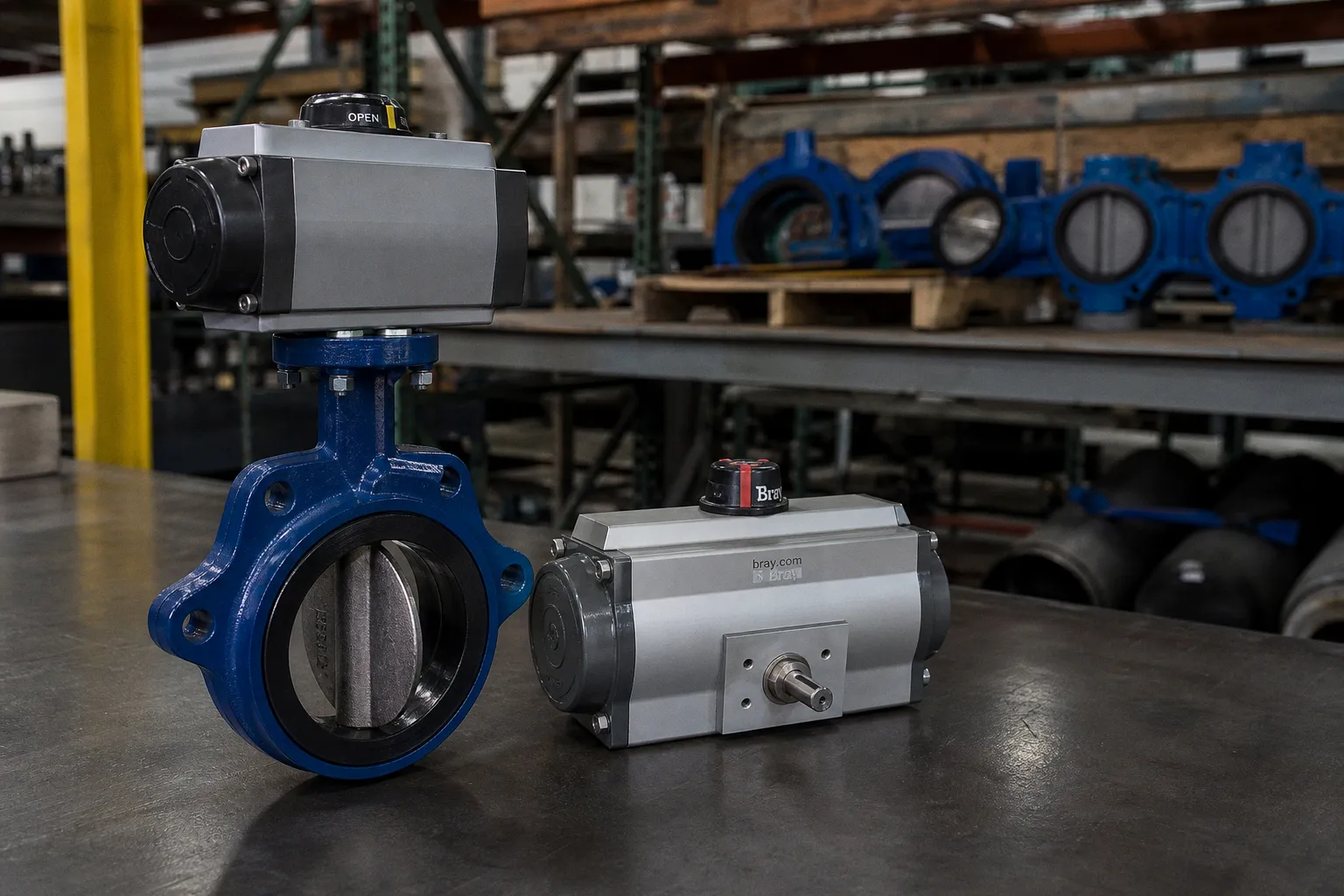
I have audited enough water-line packages to know how this ends. The actuator stalls at the seat during a cold, dirty start. Or it closes perfectly—until its peak output twists a stem, strips a coupling, or drives hard into stops that were never meant to absorb that load. Both failures begin with the same bad premise: that butterfly valve actuator sizing for industrial water lines has a universal torque-margin rule.
It does not.
The valve manufacturer owns the torque data. The actuator manufacturer owns the output curve. The engineer or package builder has to make those two sets of facts meet at the actual operating condition. Everything else is noise.
A torque margin is not a number you add by habit. It is uncertainty you either understand—or hide inside an oversized actuator.
Manufacturer torque data beats the folklore margin
“Use a 20% margin” sounds reassuring. So does 25%, 30%, or the more theatrical “just double it.” None of these phrases tells me whether the valve will work.
The problem is not that margins are bad. The problem is that manufacturer torque data do not arrive with a common accounting system.
One manufacturer may publish seating and unseating values with bearing and stem-seal friction already included. Another may publish expected torque with a built-in safety factor. A pneumatic actuator example may recommend multiplying demand by 1.2. These are not competing truths. They are different calculation boundaries. Treating them as interchangeable produces bloat at best and broken hardware at worst.
For resilient-seated butterfly valves, one manufacturer explicitly tells users not to add a safety factor to its stated seating and unseating torque when selecting actuator output. Another publishes expected seating and unseating torques that already include a 30% safety factor. Emerson’s FieldQ pneumatic sizing example, by contrast, uses a 1.2 factor.
That means the familiar “standard 20% margin” can be:
- sensible for one defined valve-and-actuator method;
- redundant for another;
- dangerously excessive when it drives maximum actuator torque above the valve stem’s allowable limit;
- insufficient where dynamic torque, deposits, low air pressure, or an unusual duty cycle sit outside the base data.
This is why I reject the phrase “standard actuator margin” in a submittal unless the calculation names the valve series, seat material, disc configuration, differential pressure, service medium, and the manufacturer’s own torque basis. Without that, the number is just corporate incense.
A rubber-seated waterworks butterfly valve under ANSI/AWWA C504 serves a broad envelope: nominal sizes from 3 to 72 inches, water types ranging from raw to reclaimed, pH from 6 to 12, and temperatures roughly 0.6 to 52°C. That is a useful standardization envelope for the valve category. It is not a universal actuator-sizing chart. A 150 mm valve in clean, regularly cycled treated water is not the same mechanical problem as a 1,200 mm valve sitting idle in a sediment-prone raw-water line.
The torque sheet is a contract, not a suggestion
Before I let anyone select an actuator, I want a traceable torque schedule from the valve manufacturer. It needs to state:
- valve make, series, nominal size, pressure class, disc style, seat material, shaft arrangement, and end connection;
- maximum differential pressure across the closed valve—not merely the pipeline pressure rating;
- seating and unseating torque at that differential pressure;
- breakaway torque if the manufacturer identifies it separately;
- dynamic torque by opening position where the valve will throttle;
- maximum allowable stem torque;
- operating medium, temperature range, solids or deposits risk, and expected cycling frequency;
- any adjustment already embedded in the published figures.
The words maximum differential pressure deserve emphasis. A valve in a 10-bar-rated line does not necessarily see 10 bar across the disc. It may see almost no differential pressure in one operating case and the full available head during isolation, pump trip, or an abnormal flow path. Conversely, it may see a condition worse than the casual design narrative admits. Actuator sizing belongs to the governing differential-pressure scenario, not to a label on the pipe drawing.
Seating torque is not proportional to valve diameter
Teams often use nominal diameter as a lazy proxy for actuator demand. Bigger valve, bigger actuator. True in the broadest, least useful sense. But the relationship is not clean, linear, or portable across designs.
Torque at the seat comes from the disc forcing through an elastomer seat while differential pressure acts on the disc. It also reflects seat friction, disc-edge finish, installed disc-to-seat interference, seat thickness, bearing friction, stem-seal friction, and the service medium. Change the seat compound or disc coating and the operating curve can move materially. Change the installation geometry between flanges and the same thing can happen.
A manufacturer’s general-service resilient-seat data illustrates the scale, not a universal answer:
| Valve size and example configuration | At 0 bar differential pressure | At 7 bar | At 12 bar |
|---|---|---|---|
| DN 100 full-disc valve | 42 N·m | 48 N·m | 52 N·m |
| DN 500 full-disc valve | 870 N·m | 1,458 N·m | 1,751 N·m |
The point is not to copy these numbers into a specification. Do not do that. They apply to a particular manufacturer’s valve series, disc configuration, service class, and stated conditions.
The point is that the pressure effect becomes substantial as the valve grows. The DN 100 example rises 10 N·m between zero and 12 bar. The DN 500 example rises 881 N·m over the same pressure range. A selector who treats both valves as “water service butterfly valves” and applies one generic margin has already stopped engineering.
For water and aqueous service, published torque charts can also separate service classes. One general-service classification covers water, aqueous liquids, and salt water where major corrosion and deposits are absent, temperature remains comfortably within seat limits, and the valve cycles at least every three to six weeks. That last condition is not decorative fine print. A valve that moves monthly behaves differently from one that stays shut through a season, collects deposits, and then receives a command during an upset.
The installed valve is the valve you need to automate
A butterfly valve torque chart usually assumes a defined installation and service basis. Real projects are less polite.
I look for the conditions that make catalogue confidence evaporate:
1. Long idle periods. Elastomer seats can stick, deposits can form, and the initial breakaway event can become the governing case. If the valve moves only for emergency isolation, do not casually use torque data intended for regular cycling.
2. Dirty or untreated water. Raw water, wastewater, scale, biological growth, suspended solids, and chemical residue can change friction and seating behavior. “It is only water” has launched more bad selections than I can count.
3. Temperature near seat limits. A seat compound does not become unpredictable only after it crosses a published maximum temperature. Performance can shift as the boundary approaches.
4. Flange-induced interference. Over-tightened bolts, poor alignment, unsuitable gaskets, or distorted pipework can alter disc-to-seat interference. The actuator does not know the installer was having a difficult Tuesday. It just sees higher torque.
5. Three-way arrangements. Where one butterfly valve opens while another closes, the actuator calculation may need a combined demand. One manufacturer’s assembly guidance uses a 1.5 multiplier for this arrangement. Again: use the package-specific rule, not a borrowed multiplier from another valve family.
“Water service” is a fluid description, not a torque calculation.
Dynamic torque is where throttling applications get exposed
For isolation duty, the usual focus lands on breakaway, seating, and unseating. That can be adequate—provided the valve genuinely acts as an on/off valve and the manufacturer confirms the torque basis.
For throttling duty, that shortcut fails.
Dynamic torque occurs while the disc sits in flowing fluid. It can vary sharply with disc angle, pressure differential, velocity, cavitation conditions, and the valve geometry. A valve may require less torque at the closed seat than it does at an intermediate opening position. So the neat calculation that compares an actuator’s end-of-stroke output to seating torque can look perfect while the actuator struggles at 45 degrees.
This is not a theoretical edge case. For resilient-seated butterfly valves, manufacturer guidance specifically calls for dynamic-torque review on 24-inch / DN 600 and larger valves in control service. The same trigger applies to valves at that size and above when velocity reaches 16 ft/s, or about 4.9 m/s.
That does not mean a 20-inch valve is automatically safe or a 24-inch valve is automatically unsuitable. It means the risk stops being small enough to ignore. At larger diameters, fluid forces and the cost of a bad assumption both become very real.
Build the torque envelope across the stroke
For a modulating butterfly valve, I want an angle-by-angle comparison. Not a single “required torque” cell in a spreadsheet that has mysteriously lost its source.
The working envelope should show the valve’s required torque at the relevant disc positions and the actuator’s available output at those same positions, under the minimum available motive power.
For a pneumatic actuator, the basic logic is blunt:
Available actuator torque at each critical position and minimum supply pressure must exceed the required valve torque at that same position.
Then the second half of the sentence:
Maximum actuator torque under the highest credible supply pressure must remain below the valve’s maximum allowable stem torque.
This two-sided check catches the design pattern that causes trouble in both directions. A small actuator may lack torque when air pressure sags. An oversized actuator may survive every low-pressure scenario but overpower the valve during normal or high-pressure operation.
For a double-acting pneumatic actuator, the opening and closing torque curves can differ. For a spring-return unit, spring torque changes through travel and may make one direction more constrained than the other. Do not compare a catalogue’s headline torque figure with one valve torque number and walk away. That is brochure arithmetic.
For electric actuator sizing for industrial valves, the same discipline applies, with different failure modes. Motor output, gear train, duty cycle, start frequency, control accuracy, thermal limits, and available power all matter. An electric actuator that reaches rated torque briefly is not automatically suitable for repeated modulation. If the line asks the actuator to hunt around a control position all day, thermal and duty-cycle limits become part of the torque story.
Pneumatic actuator torque calculation: use minimum air, then protect the stem
Pneumatic packages produce a special kind of false comfort because compressed air sounds abundant. It often is—right up until several valves move at once, a compressor cycles, a regulator drops pressure, cold weather changes the system, or a long instrument-air run turns a nominal pressure into wishful thinking.
I size pneumatic actuators against minimum available supply pressure at the actuator, not against the number printed on the compressor room gauge.
That is also the logic in established pneumatic sizing practice: actuator output must exceed the sizing torque at minimum supply pressure, while maximum actuator output must stay below the valve’s allowable stem torque. Both conditions matter. Neither substitutes for the other.
A disciplined pneumatic actuator torque calculation follows this order:
1. Define the worst valve demand. Use valve-maker data at maximum applicable differential pressure. Include seating and unseating torque, plus dynamic torque for throttling or high-velocity duty.
2. Identify whether published valve torque already includes an allowance. This determines whether a manufacturer-approved factor applies. Never stack a generic 20% factor on top of a value that already includes 30% simply because the spreadsheet has a margin column.
3. Map torque against travel. Record requirements at closed, intermediate, and open positions where applicable. For a control valve, the peak may sit in the middle.
4. Use the actuator’s actual torque curve. Double-acting rack-and-pinion, scotch-yoke, vane, and spring-return designs do not deliver identical torque through the stroke. The shape matters.
5. Check the low-pressure case. Use the minimum supply pressure at the actuator after realistic regulator, piping, filter, and system losses.
6. Check the high-pressure case. Confirm the actuator cannot exceed the valve’s maximum allowable stem torque. This includes abnormal but credible supply conditions, not just the preferred regulated setpoint.
7. Verify the mechanical chain. The ISO 5211 interface defines mounting-flange and drive-component dimensions and reference interface values. It does not magically calculate valve operating torque. Check the mounting kit, coupling, keys, brackets, travel stops, and alignment as components with their own limits.
The last point gets neglected because interface standards make assemblies look plug-and-play. They are not. An ISO mounting pattern helps the actuator attach. It does not certify that the coupling transmits the torque safely, that the bracket stays rigid under load, or that the stop bolts can absorb repeated impact from an over-energized actuator.
Electric actuator selection is not “pneumatic sizing with a cable”
Electric quarter-turn actuators invite another bad shortcut: select a motorized unit with a nominal output above the valve’s listed breakaway torque, then treat the project as complete.
The electrical package has its own friction.
Start with the required valve torque envelope, just as you would for air. Then inspect what the electric actuator can actually deliver under its stated voltage, duty classification, ambient temperature, control mode, and cycling demand. A unit rated for infrequent isolation may not tolerate continuous modulation. A control package may need position feedback, deadband control, a suitable resolution, and a duty rating that survives the actual command profile rather than the clean one on the P&ID.
Fail position changes the conversation too. A pneumatic spring-return actuator can move to fail-open or fail-close using stored spring energy, but that stored energy must still meet the torque envelope in the relevant direction. An electric actuator may hold position, drive to a defined position with backup power, or use another safety architecture. “Fail safe” is not a product checkbox. It is a process requirement translated into torque, time, energy source, and valve position.
And then there is closing speed.
I see specs that demand “fast closing” for isolation and “slow closing” to avoid water hammer, often in adjacent paragraphs. No universal valve-closing time solves water hammer. The acceptable travel time depends on the pipeline’s transient behavior, line length, wave speed, pump dynamics, upstream and downstream boundary conditions, and control strategy. A faster actuator can protect one failure scenario while making another worse. That calls for transient analysis, not a casually chosen 10-second or 30-second setting.
A practical route through the selection mess
I do not need every project to become a doctoral thesis. I do need it to stop pretending that nominal valve size is a torque input.
For an industrial water line, the route is straightforward:
| Decision point | What drives the answer | Common bad shortcut |
|---|---|---|
| Valve torque | Manufacturer data at maximum differential pressure and actual service | Using line pressure rating or valve diameter alone |
| Margin method | The valve-maker’s stated data basis and package guidance | Adding 20–30% because “that is what we always use” |
| Throttling duty | Dynamic torque through the operating travel | Checking seating torque only |
| Pneumatic actuator output | Minimum pressure at the installed actuator | Using nominal plant air pressure |
| Maximum load | Valve stem limit, coupling, mount, and stops | Selecting the largest actuator that fits |
| Electrical package | Torque, duty cycle, voltage, thermal limit, control behavior | Choosing by peak torque only |
| Closing time | Pipeline transient analysis and process duty | Declaring one universal anti-hammer time |
The bureaucracy around valve automation tends to produce large submittal packages and small amounts of actual reasoning. Cut through it. Ask for the torque curve. Ask what is included in it. Ask where the pressure number came from. Ask whether the valve throttles. Ask what happens when supply air is low and when it is high.
If those answers are missing, the actuator selection is not conservative. It is unfinished.
The blunt verdict
I would not approve a butterfly valve actuator because it has “a healthy margin.” That phrase tells me nothing until I see the manufacturer’s torque basis and the actuator curve at real operating conditions.
Do this: size from the specific valve’s published demand at maximum differential pressure, assess dynamic torque for control and high-velocity large-diameter service, use minimum pneumatic supply pressure, and cap maximum output below allowable stem torque.
Not that: pick by nominal size, borrow a 25% factor from another project, and bolt on the biggest actuator procurement can still ship this quarter.
That is not a safety margin. That is over-engineered uncertainty with a purchase order attached.