Pump shaft seal replacement: pre-service data and parts checklist
Most seal failures I get called to look at were not caused by the seal. They were caused by the week before the seal: a parts order matched to shaft diameter and nothing else; an installer treating a…
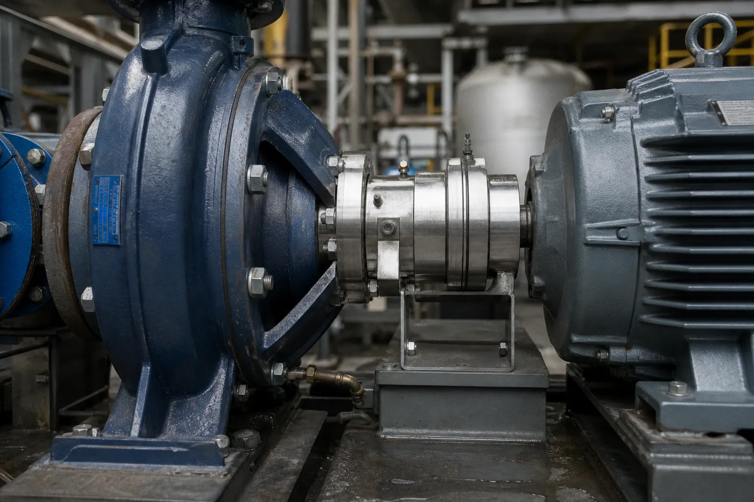
Most seal failures I get called to look at were not caused by the seal. They were caused by the week before the seal: a parts order matched to shaft diameter and nothing else; an installer treating a closed discharge valve as isolation; a shop reusing cup-point grub screws because the new ones were not on the bench.
Those are pre-service failures. They arrive before anyone touches a gland bolt.
I have audited enough of these jobs to know the pattern. A work order says “centrifugal pump, change seal.” Purchasing matches dimensions. Maintenance fits the cartridge. The pump goes back into service with the same sleeve damage, the same wandering shaft, the same blocked flush line, and the same unexamined process conditions that killed the previous seal. Then everybody calls it a seal failure.
A proper pump shaft seal replacement preparation checklist is not bureaucratic decoration. It is how a maintenance team removes the conditions that drive premature seal failures before a new component is asked to survive them.
Capture the data that actually selects the seal
Matching a mechanical seal by shaft diameter is the cheapest route to an expensive repeat job. A seal may physically fit the sleeve and still fail quickly because the fluid attacks the face materials, the temperature is outside the elastomer’s useful range, the chamber pressure changes the operating margin, or an auxiliary service assumed unnecessary is essential to the arrangement.
The useful starting point is the application data, not the old part number. Existing seal identification matters, but it is evidence, not an instruction. The old seal may have been wrong from the day it was installed.
For centrifugal pump seal change data, collect the information that determines both geometry and duty:
- Pump manufacturer, model, serial number, and nameplate details. Record the pump, not merely the skid tag or the process line designation.
- Shaft or sleeve outside diameter, measured at the seal location rather than copied from an old bill of materials.
- Shaft rotation viewed from the drive end. “Clockwise” without a viewing direction is how parts get ordered incorrectly.
- Seal chamber dimensions, including gland pilot, bore, face condition, and available axial space, checked against the seal drawing.
- Process fluid identity and behavior: specific gravity, seal-chamber pressure, vapor pressure, temperature, viscosity, solids, and any tendency to crystallize, coke, polymerize, or flash.
- Buffer or barrier fluid specification where the seal arrangement uses one.
- Existing seal type, failure history, and any change in process conditions since the last installation.
The last point is routinely missed. A pump may still have the same tag and the same motor while its duty has changed materially. A product blend may run hotter. A recirculation line may have been altered. A control valve may now spend more time throttled. The seal sees those changes whether the maintenance record mentions them or not.
Miss vapor pressure on a light hydrocarbon service and a seal can lose its liquid film at exactly the wrong moment. Miss the real temperature window and the elastomer selected from the old BOM may harden, swell, or lose its resilience. Match the geometry while ignoring chemistry and operating conditions, and you have bought a leak with a part number on it.
A seal drawing tells you what can fit. Application data tells you what has a chance of living.
The OEM pump manual and the seal layout drawing outrank the assumptions on the bench. Generic manufacturer tables are useful guardrails, especially when the equipment record is thin, but they are not permission to disregard the specific seal arrangement. If the pump manual, seal drawing, and actual measured equipment condition disagree, stop and resolve the conflict before ordering parts.
Verify shaft movement and chamber geometry before the old seal comes out
The replacement cartridge usually arrives before anyone has proved that the pump can carry it. That is backwards.
A seal cannot correct shaft runout, excessive end float, poor chamber-face squareness, or a gland pilot running out of concentricity. It only has to endure the consequences: uneven face loading, distorted secondary seals, fretting, heat generation, and leakage that gets blamed on the component instead of the machine.
Flowserve publishes general guidance for pumps with ball or roller bearings operating in the 1,000–3,600 rpm range. It is a sensible reference point when there is no seal-specific drawing immediately available:
| Parameter | Flowserve general guidance |
|---|---|
| Shaft runout, measured at the seal location | ≤ 0.05 mm (0.002 in) TIR |
| Shaft endplay | ≤ 0.25 mm (0.010 in) TIR |
| Seal-chamber face squareness | ≤ 0.0005 mm/mm (0.0005 in/in) of bore TIR |
| Shaft-to-chamber-bore or gland-pilot concentricity | ≤ 0.025 mm per 25 mm of shaft diameter, capped at 0.125 mm (0.005 in) TIR |
Those figures are general values, not a substitute for the mechanical seal swap requirements on the actual drawing.
A cartridge specification can be much tighter. The John Crane Type 8628VL, for example, calls for end float no greater than 0.005 in F.I.M., seal-chamber-face runout no greater than 0.0005 in per inch of bore, chamber-bore concentricity no greater than 0.005 in F.I.M., and shaft runout at the seal location no greater than 0.001 in F.I.M.
That shaft runout figure is substantially tighter than the general pump guidance. It is not fussy drafting. A stationary-face cartridge seal does not have much appetite for shaft wobble. The stationary face stays where the gland put it; the rotating hardware follows the shaft. Excess movement turns a controlled sliding interface into a component trying to accommodate machine error.
Measure before stripping the pump down far enough to lose the evidence. Put the indicator where the seal actually runs, not at a convenient clean section of shaft elsewhere. Check end float with the shaft moved in both directions. Inspect the bearings, shaft sleeve, coupling condition, and baseplate alignment when the readings are poor. Do not install a new cartridge and hope the new hardware will somehow stabilize a worn rotating assembly.
“We’ll shim it” is not a corrective action unless the drawing specifically calls for a defined shim procedure and the underlying dimensions are known. Otherwise it is a prayer with a torque wrench.
Generic tolerance tables are guardrails. The seal drawing and OEM limits decide the job.
Surface finish is part of the sealing system
Surface finish gets ignored because it is less dramatic than a cracked sleeve or a visibly damaged face. That does not make it optional.
The gland gasket needs a proper housing face. The secondary seal needs an acceptable sleeve surface. The gland pilot and chamber bore need to locate the assembly without scoring, cocking, or damaging elastomers during installation. A seal chamber can look clean and still present the new cartridge with a poor reference surface.
Common finish requirements used for this work are:
- Seal-housing face: no rougher than 1.6 μm (63 μin) Ra.
- Housing bore: no rougher than 3.2 μm (125 μin) Ra.
- Shaft or sleeve: no rougher than 0.8 μm (32 μin) Ra.
These values need to be read alongside the particular seal drawing. The point is not to turn every shutdown into a metrology exercise. The point is to avoid fitting precision sealing hardware onto a sleeve with a deep track under the O-ring, a housing face bruised by an over-torqued gland, or a bore that has been raised with burrs during the last removal.
A sleeve that has run for years can be deceptive. The polished band may look acceptable until it is checked under good light and with a fingernail across the secondary-seal travel area. Grooves, pitting, corrosion, embedded solids, and heat checking all matter. Hand-polishing may remove a sharp edge or light staining, but it does not reliably restore a damaged sleeve to the surface and dimensional condition the seal needs.
Likewise, a damaged housing face should be corrected before the cartridge goes on. The gland gasket is not there to compensate for dents and distorted studs. If the face is out of condition, machine it or replace the part. A new seal deserves a valid reference surface.
Lockout, tagout, and the closed-valve fiction
A closed valve is a flow-control device. It is not automatically an isolation boundary.
I have walked onto jobs where a technician was ready to crack a seal chamber with the discharge valve shut and the suction side separated only by a single butterfly valve. That is not isolation. It is optimism with a wrench.
The energy-control process has to cover shutdown, isolation of every energy source, lockout or tagout, control of stored energy, and verification that the isolation works. Verification is the word teams skip when the pump has been down for an hour and somebody wants it running by lunch.
Before seal work begins:
1. Shut down the pump according to the site procedure and isolate electrical, mechanical, hydraulic, pneumatic, thermal, and process energy sources that can affect the work.
2. Apply lockout/tagout at every defined isolation point. Do not assume the motor disconnect is the entire job if the pump can be driven, pressurized, heated, or back-fed from elsewhere.
3. Drain the pump and seal chamber through the correct connection. Vent safely and release pressure completely.
4. Confirm the gauge reads zero where a gauge is available, while remembering that a blocked gauge connection can lie just as effectively as a closed valve.
5. Attempt a start in accordance with the site procedure and verify there is no movement.
6. Treat the chamber as potentially live until it has been vented, drained, and proved safe to open.
A chamber that appears empty can retain trapped pressure, hot liquid, vapor, or residual product in a dead leg. The gland bolts do not know whether the work order says “isolated.” They only know what remains behind them.
The job also needs the documentation and installation hardware present before disassembly turns into a scavenger hunt: pump operating manual, seal installation drawing, mechanical seal, shrink disc where applicable, and the required assembly aids. No manual and no drawing is not a minor inconvenience. It is a reason to pause.
And if the kit uses cup-point grub screws, use new ones. The old screw has already been loaded into the shaft surface. Its point may be flattened, damaged, or unable to achieve the intended grip. Reusing it because it is within reach is how a drive collar starts walking and the seal gets destroyed behind it.
Auxiliary services are not optional plumbing
Every seal arrangement has a thermal and lubrication story. The piping plan is part of that story.
For a single seal, that may mean confirming a recirculation or flush path is clean, open, and actually reaching the chamber. For a dual seal, the barrier or buffer system is not an accessory installed for appearance. Its fluid condition, pressure, level, cooling, circulation, and connections determine whether the faces operate in the environment they were selected for.
The names vary by arrangement: Plan 11, Plan 23, Plan 52, Plan 53A, or another plan identified on the seal drawing. The discipline does not vary. If the seal requires an auxiliary fluid system and the system is not connected, vented, filled, and functional, the installation is unfinished.
Work through the services in the order the equipment will depend on them:
- Confirm recirculation, flush, heating, cooling, and quench lines are connected to the right ports. A line connected to the wrong side of the gland can be worse than a missing line.
- Make sure block valves are in their required operating positions and that no temporary blinds, plugs, or hose connections from maintenance remain in the circuit.
- Prove flow or circulation at the seal chamber where the arrangement requires it. An upstream gauge only proves pressure exists somewhere upstream.
- Vent the chamber as called for by the drawing, then fill it with liquid where the arrangement requires a flooded chamber.
- Check the barrier-fluid reservoir for the correct level and condition. Where a gas blanket is specified, set it to the pressure stated on the drawing or plant procedure.
- Turn the shaft by hand before coupling connection and again after the seal is fitted, following the manufacturer’s installation procedure.
The free-rotation check is simple enough that it gets treated casually. It should not. If the shaft does not turn freely, find out why before startup. Possible causes include bearing damage, coupling stress, pipe strain, a displaced sleeve, an incorrectly set cartridge, or an installation error. A seal is not a diagnostic tool for those problems.
A dry start on a seal intended for a flooded chamber can damage faces in the time it takes to reach speed. The startup itself may look normal. The damage report arrives later.
Standards are references until the duty and contract make them requirements
API Standard 682, Pumps—Shaft Sealing Systems for Centrifugal and Rotary Pumps, is in its fifth edition. ISO 21049:2004 addresses the same subject and was confirmed current in June 2021. Their stated scope is petroleum, natural-gas, and chemical-industry service, with particular relevance to hazardous, flammable, or toxic duties.
That scope matters because standards get waved around too casually in meetings.
For a non-hazardous water pump in general industrial service, API 682 can be an excellent technical reference without being the governing requirement. The applicable seal arrangement may instead be determined by the pump OEM, site engineering standard, customer specification, insurer requirements, local regulations, or the consequences of a leak.
A flammable-hydrocarbon duty in a classified area deserves serious scrutiny, but it does not mean API 682 automatically governs every installation. Establish which documents are contractually and technically applicable to that specific pump, then select the seal system and auxiliary plan accordingly. The hazard assessment, plant standards, OEM guidance, and process conditions all belong in that decision.
Both standards address pump shaft diameters from 20 mm (0.75 in) to 110 mm (4.3 in). Outside that range, the standards are less useful as a selection map and the OEM manual, seal manufacturer drawing, and equipment-specific engineering review carry even more weight.
What needs to be on the bench before the install starts
The practical value of a gland packing replacement data checklist or mechanical seal preparation sheet is not that it makes a job look organized. It prevents the crew from discovering missing information after the old seal is out and the pump is unavailable.
Before the first gland nut comes loose, the job package should contain:
- Measured shaft or sleeve OD, rotation direction, pump identification, and confirmed seal chamber dimensions.
- Process-fluid data, including the real pressure and temperature window at the seal chamber, not only nominal line conditions.
- The seal installation drawing and pump operating manual.
- Documented readings for runout, end float, chamber-face squareness, concentricity, and relevant surface condition.
- The replacement seal with its part number checked against the drawing and application.
- Correct gland gasket, sleeve, drive collar, setting clips, fasteners, and assembly aids.
- New cup-point grub screws where the design calls for them.
- A completed isolation and depressurization process, verified rather than assumed.
- Confirmed readiness of flush, quench, cooling, recirculation, buffer, or barrier services.
- A plan to verify shaft freedom of movement and remove setting clips at the correct point in the manufacturer’s procedure.
That is the boring part. It is also the part that separates a controlled repair from an expensive experiment conducted on a live process pump.
The seal should be the final component in a chain of correct decisions: correct duty, correct geometry, acceptable machine condition, safe isolation, proper installation hardware, and functioning auxiliary services. Get those conditions right, and the new seal starts life with a fair chance. Skip them, and the failure report has usually been written before the pump is even restarted.