Industrial pump shaft alignment tolerances for reliable operation
At 3,600 rpm, a parallel offset of ±0.75 mils is only acceptable guidance. Excellent alignment is ±0.5 mils. Angular misalignment is tighter still: 0.2 mils excellent, 0.3 mils acceptable.
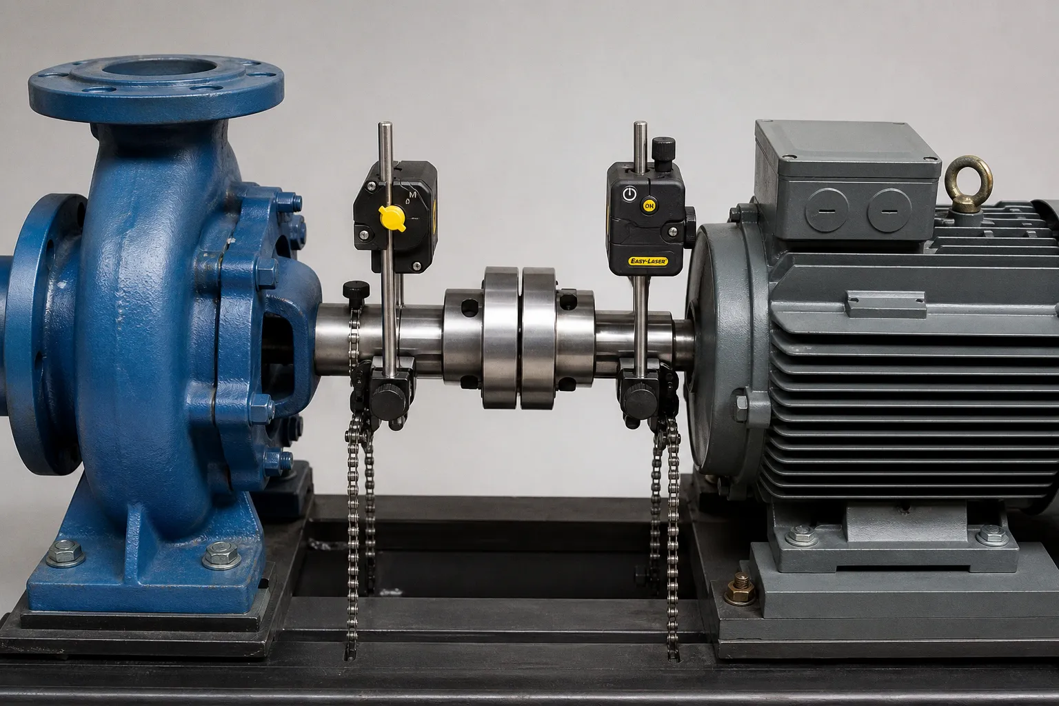
That is the scale of the problem. One mil is 0.001 inch. A coupling can look centered. A dial indicator can show a number that appears small. The machine can still convert that error into bearing load, seal distress, vibration, and reduced throughput.
Industrial pump shaft alignment tolerances are not one universal number printed on a maintenance poster. They depend on speed, coupling geometry, machine configuration, operating temperature, and the pump and coupling OEM requirements. The correct workflow is therefore not “align to zero.” It is: establish the machine condition, remove external forces, measure correctly, apply the relevant target, then validate the result at operating temperature.
Speed-dependent tolerance tiers for centrifugal pumps
Rotational speed compresses the available error budget. A pump train at 1,200 rpm can tolerate more lateral and angular deviation than the same architecture operating at 3,600 rpm. This is not a cosmetic distinction. Higher speed increases the consequence of coupling misalignment and narrows the margin before vibration and component load become operational problems.
The U.S. Department of Energy publishes typical alignment guidance that illustrates the progression.
| Motor speed | Parallel offset: excellent | Parallel offset: acceptable | Angular misalignment: excellent | Angular misalignment: acceptable |
|---|---|---|---|---|
| 1,200 rpm | ±1.25 mils | ±2.0 mils | 0.5 mils | 0.8 mils |
| 1,800 rpm | ±1.0 mils | ±1.5 mils | 0.3 mils | 0.5 mils |
| 3,600 rpm | ±0.5 mils | ±0.75 mils | 0.2 mils | 0.3 mils |
These are typical DOE guidance values. They are not a universal ANSI, API, ISO, or OEM acceptance specification. Treating them as universal creates a documentation-shaped failure: the work order closes, but the machine remains outside the actual coupling or pump requirement.
A maintenance team should use the table as a routing mechanism:
1. Identify running speed first. A target suitable for a 1,200-rpm cooling-water pump is not a target for a 3,600-rpm process pump.
2. Obtain the coupling requirement. Flexible couplings accommodate some misalignment. They do not erase the loads created by misalignment. The allowable value from a coupling supplier is also not automatically the preferred operating target for a critical pump.
3. Check the pump OEM instruction. One Flowserve HWMA instruction, for example, states a maximum parallel shaft offset at working temperature of 0.05 mm, or 0.002 inch. That is a model-specific limit, not a fleet-wide rule.
4. Specify the measurement convention. Offset, angularity, rim-and-face readings, reverse-dial output, and laser results can be reported differently. A number without method and reference plane has low diagnostic value.
5. Record the condition of measurement. Cold, warmed, uncoupled, coupled, before piping, and after piping are different system states. Combining them in one report destroys traceability.
The word “acceptable” also needs restraint. It means a machine may meet a typical field tolerance. It does not mean the result is optimal for energy use, bearing life, seal stability, or repeatability. For critical or high-speed services, the excellent band is the rational target when installation conditions permit it.
The alignment target is not a single number. It is a speed-, coupling-, temperature-, and system-condition requirement.
ANSI/ASA S2.75 provides the method, not a shortcut
ASA/ANSI S2.75-2017 Part 1, Shaft Alignment Methodology: General Principles, Methods, Practices, and Tolerances, remains a relevant reference and was reaffirmed in 2025. Its value is methodological. It frames alignment as a controlled measurement and correction process rather than a final indicator reading.
The series also includes Part 2 vocabulary and a 2021 Part 3 addressing vertically oriented rotating machinery. That distinction matters. A horizontally mounted motor-driven centrifugal pump and a vertical rotating train do not present the same gravitational, thermal, and measurement conditions.
For a standard horizontal pump-motor set, the sequence is straightforward but often executed in the wrong order:
1. Establish the stationary machine
The driven equipment is normally secured first. In a pump set, that means the pump remains fixed and the motor is moved into alignment.
Moving the pump may appear convenient because pump feet are accessible or the motor base is crowded. It is usually the wrong system decision. The pump is connected to suction and discharge piping. Shifting it can transfer displacement into flanges, nozzles, pipe supports, and connected equipment. The laser display may improve while piping stress increases.
Motor movement preserves the pump’s installed position and confines correction to the machine intended to be movable.
2. Correct soft foot before precision alignment
Soft foot is not a minor baseplate issue. It is a measurement contaminant. If a motor foot lifts, rocks, or deflects when bolts are tightened, each bolt torque sequence can produce a different shaft position. Alignment data then has high latency: the displayed condition does not represent the condition after final tightening.
The cited ANSI/ASA guidance identifies 0.05 mm, or 2 mils, as the soft-foot tolerance. This is a practical threshold. Above it, shimming and alignment corrections can become a loop with no stable endpoint.
The correction process needs to distinguish among common conditions:
- Parallel soft foot: one foot is uniformly unsupported. Shim correction may resolve it.
- Angular soft foot: the foot contacts at one edge. The base, foot, or shim stack may need correction rather than added shims.
- Induced soft foot: tightening one bolt pulls the machine frame into distortion. This can indicate a baseplate, hold-down, or foot geometry issue.
- External-force response: the shaft moves when pipe supports, conduit, or attachments are released. This is not soft foot. It is an installation-load problem.
Adding shims to compensate for pipe strain is an error. It may create an acceptable cold reading, but it leaves the pump casing under external load.
3. Measure the coupling geometry with the correct tool logic
Laser shaft alignment procedures reduce reading and calculation error, particularly where shaft rotation is restricted or where the machine geometry is complex. They do not eliminate setup error.
A laser system still requires clean mounting surfaces, rigid brackets, correctly entered distances, compensation for shaft rotation, and a stable machine. Loose brackets, backlash in adjustment bolts, damaged coupling hubs, or distorted feet can produce clean-looking output with poor field validity.
Dial indicators can also achieve precise results when used with disciplined setup and an appropriate method. The risk is not the dial itself. The risk is unrecorded sag compensation, excessive bracket flex, incorrect interpretation, and the habit of accepting a single reading without repeatability.
The method should produce the same result after a controlled remount and repeat rotation. If it does not, do not average away the variation. Find its source.
Pipe strain is an alignment failure source, not a secondary detail
A pump can be aligned accurately on an isolated baseplate, then be pulled out of tolerance when suction and discharge piping are bolted up. This sequence is common because installation teams often treat piping connection as a downstream activity. It is not downstream. It is part of the alignment system.
Pump OEM instructions commonly require alignment to be checked again after piping is connected. The cited Flowserve instructions state that piping must be aligned without residual stress or external force. The stated consequences are direct: misalignment, hot bearings, worn couplings, vibration, and possible pump failure.
The cited ANSI/ASA requirement limits alignment change caused by piping, flange strain, conduit strain, or attached ductwork to no more than 50 micrometers, or 2 mils, vertically or horizontally at the coupling.
This number is operationally useful because it converts a vague installation claim—“the pipe fits”—into a measurable acceptance condition.
A pipe-strain test should be part of the commissioning sequence:
1. Complete a preliminary alignment with the pump and motor mechanically stable.
2. Record the coupling alignment result.
3. Connect the piping using supports that carry pipe weight independently of the pump.
4. Re-measure alignment after flange bolts are tightened.
5. Compare the before-and-after values at the coupling.
6. If movement exceeds the applicable limit, correct the piping condition. Do not compensate at the motor feet and declare success.
The correction may involve pipe support elevation, spring support setting, flange fit-up, spool-piece geometry, thermal support design, or nozzle-load review. The point is constant: the pipe must arrive at the pump flange without forcing the pump into position.
Coupling misalignment symptoms often appear after this step has been skipped. The pattern includes elevated vibration, repeated coupling element wear, hot bearing housings, seal degradation, and alignment values that change between outage checks. None of those symptoms independently proves misalignment. Together, especially after piping work, they warrant a root-cause review of external load.
If tightening a pipe flange changes coupling alignment, the alignment task is not complete. The piping task is not complete.
Cold alignment is only an interim state
A pump and motor do not remain in their cold positions once process conditions stabilize. Motors, pump casings, bearing housings, baseplates, piping, and supports grow at different rates and in different directions. A perfectly aligned stopped machine can be misaligned during operation.
The required correction is commonly called a thermal offset or thermal growth target. It should come from OEM data or measured machine behavior. It cannot be calculated reliably from a generic rule because the necessary inputs vary:
- operating temperatures of the motor and pump;
- material and geometry of the casings, feet, shafts, and baseplate;
- centerline heights;
- motor mounting configuration;
- pump service and heat transfer path;
- piping restraint;
- support structure and surrounding ambient conditions.
Without those inputs, a cold target expressed as a precise vertical or horizontal offset is false precision.
The correct operating model is simpler. If the OEM provides thermal-growth values, use them. Enter the specified targets into the laser alignment system or apply them through the chosen measurement method. If no reliable target exists, establish a controlled baseline and verify the machine after it has run long enough to reach temperature stability.
That recheck is not optional on temperature-sensitive or critical services. DOE guidance explicitly recommends alignment verification after thermal stabilization because cold alignment can shift under operating thermal growth.
The recheck should be planned, not improvised. It requires safe access, a defined measurement method, and a record of operating conditions. “Hot” is not a useful state description. Capture pump service condition, approximate operating duration, observed casing and motor temperatures where available, and whether the machine was at stable duty.
For maintenance planning, thermal verification changes the throughput of the reliability process. It may add time to commissioning, but it reduces repeat corrective work. A one-shift alignment that must be redone after vibration trends rise has lower net throughput than a controlled cold-and-hot validation sequence.
TIR, shaft runout, and alignment data are not interchangeable
The phrase “centrifugal pump shaft runout limits” is often used during alignment discussions. This creates avoidable confusion.
Shaft runout describes variation caused by shaft geometry, hub condition, mounting surfaces, or rotation. Alignment describes the relative centerline position and angle of two coupled shafts. Runout can corrupt alignment measurements, but it is not itself the same condition as misalignment.
Total indicator reading, or TIR, also requires correct interpretation. In the cited Flowserve instruction, TIR is twice the actual shaft displacement. A 2-mil TIR reading does not automatically mean the shaft center is displaced by 2 mils. Under that convention, the actual displacement is 1 mil.
This is a frequent documentation error. A work order may list “1 mil alignment” without stating whether that is actual offset, TIR, peak-to-peak movement, or a laser-calculated value at a specified plane. The data cannot then be compared meaningfully with a tolerance.
A usable alignment record should state:
- pump identifier, motor identifier, coupling type, and running speed;
- tool and method used, including any laser system model or dial arrangement;
- condition of the coupling and hubs before measurement;
- soft-foot results by foot and bolt condition;
- before-piping and after-piping alignment values;
- horizontal and vertical offset and angular values;
- the reference plane or measurement convention;
- cold or operating-temperature condition;
- OEM thermal target, if applicable;
- final bolt-tightened verification values;
- corrective actions performed and remaining constraints.
This is not paperwork for its own sake. It reduces cognitive load during the next outage. A technician should not need to infer whether the historic result was measured before pipe connection, at ambient temperature, or after the motor was disturbed.
A practical root-cause path for pump motor vibration troubleshooting
Alignment should be investigated as a causal chain, not as a default explanation for every vibration problem. The following order prevents unnecessary motor movement and limits diagnostic churn.
1. Confirm the symptom pattern. Note whether vibration is steady, load-dependent, temperature-dependent, or newly present after maintenance. Record bearing temperature, coupling condition, seal behavior, and process changes.
2. Inspect the mechanical boundary. Check baseplate condition, anchor bolts, grout integrity, hold-down hardware, coupling element condition, and obvious looseness. Precision alignment on an unstable base has low value.
3. Measure soft foot. Resolve machine-foot instability before treating the final alignment result as real. A soft-foot condition above the applicable tolerance can change shaft position when bolts are tightened.
4. Measure initial alignment. Capture both offset and angular values with the machine in its current state. Do not correct before recording the baseline.
5. Test pipe strain. Compare the alignment condition before and after piping is connected or restraint conditions change. A shift at the coupling identifies an external-force path.
6. Apply motor corrections. Keep the pump fixed unless a documented engineering decision requires otherwise. Use vertical shimming and horizontal movement in controlled increments. Re-tighten and re-measure after each correction.
7. Validate at temperature. Where operating thermal growth is material, compare the running condition against the intended operating target rather than the cold zero point.
8. Trend the result. If vibration, bearing temperature, or coupling wear persists despite stable alignment, move to the next cause: imbalance, bearing damage, hydraulic instability, resonance, looseness, or process-induced excitation.
This sequence has a lower error rate than aligning first and diagnosing later. It also prevents an alignment technician from being used as a compensating mechanism for piping and foundation defects.
The tolerance is only valid when the installation is stable
Industrial pump shaft alignment tolerances are useful because they define a narrow geometric target. They fail when teams treat the target as detached from base condition, piping forces, thermal movement, and measurement convention.
The best alignment result is not the smallest number displayed during a cold outage. It is the most repeatable shaft relationship at operating condition, with the motor bolted, the piping connected without strain, and the machine producing stable vibration and temperature behavior.
Use these design and maintenance heuristics:
- Set the tolerance from pump speed, coupling geometry, OEM instructions, and operating temperature. Do not reuse a generic fleet value without context.
- Hold the pump position. Move the motor unless engineering review establishes another correction strategy.
- Eliminate soft foot before fine alignment. A 2-mil soft-foot condition can invalidate the final reading.
- Measure alignment before and after piping connection. A coupling shift beyond the applicable limit is a piping correction task.
- Label every result by method, reference plane, temperature condition, and TIR convention.
- Treat laser output as measurement data, not as an automatic decision. Setup quality and machine stability still control accuracy.
- Recheck machines after thermal stabilization when temperature growth can move centerlines.
- Use vibration and bearing-temperature trends to validate the operating result, not merely the shutdown measurement.