Pump bearing failure: hidden causes of premature wear
SKF attributes roughly 36% of premature bearing failures to incorrect lubrication or inadequate lubricant application. Another 14% is associated with contamination. In a pump system, those figures do not describe isolated maintenance mistakes.
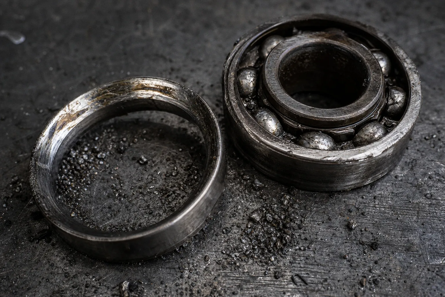
They expose a failure chain with too many uncontrolled interfaces: storage, assembly, shaft alignment, piping loads, seal condition, operating point, and monitoring latency.
Industrial pump bearing failure causes are routinely reduced to “the bearing wore out.” That diagnosis has low value. A bearing is usually the visible casualty of a system-level defect. Replacing it without identifying the damage mode and the load path produces repeat failures, elevated maintenance throughput, and unreliable mean-time-between-repair data.
The correct question is not whether the bearing failed. It is what imposed the damaging condition, how long it remained active, and why the maintenance process did not detect it earlier.
The anatomy of failure: fatigue is only one damage mode
A failed rolling bearing should be classified before a replacement order is raised. ISO 15243:2017 separates in-service rolling-bearing damage into six categories:
1. Rolling-contact fatigue. Repeated stress eventually creates surface-origin or subsurface-origin damage. It is often linked to overload, incorrect internal clearance, shaft deflection, or a duty cycle outside the bearing’s intended envelope.
2. Wear. Abrasive particles, inadequate film thickness, or incorrect lubricant selection remove material progressively. The running surfaces lose geometry before they fail visibly.
3. Corrosion. Water ingress, process leakage, condensation, and chemically degraded lubricant can etch raceways and rolling elements. A corroded surface becomes an efficient generator of vibration and debris.
4. Electrical erosion. Stray shaft current can pass through the bearing, producing fluting or other electrical damage. Variable-frequency-drive applications require this possibility to be treated as a design condition, not an exotic exception.
5. Plastic deformation. Incorrect mounting, impact loading, or severe static loading can create dents and indentations. The bearing may run for a period after installation, then produce periodic vibration as rolling elements pass the damaged zone.
6. Cracking and fracture. This is usually a terminal event. It can follow overload, mishandling, material defects, or severe installation errors.
This classification changes the investigation. “Bearing fatigue” and “contamination” are not interchangeable labels. Fatigue describes repeated stress damage. Contamination describes an input condition that may accelerate wear, disrupt lubrication, initiate surface distress, and then create secondary fatigue.
The damage pattern must be read against the complete machine. That includes the pump, motor, coupling, baseplate, foundation, seal arrangement, bearing housing, suction and discharge piping, and recent operating history.
A bearing failure report that ends at the bearing is not root-cause analysis. It is a parts record.
Premature bearing wear in centrifugal pumps often follows a predictable sequence. A small alignment error or piping load increases radial or axial load. Lubrication film thickness drops at a loaded contact zone. Wear debris enters the lubricant. Vibration rises. The seal runs with more shaft movement. Leakage or external contamination follows. The replacement bearing then inherits the same system conditions.
The system is not complicated because the components are obscure. It is complicated because each component can hide the origin of the next failure signal.
Lubrication and contamination: two separate failure paths
Lubrication failure signs in industrial pumps are frequently interpreted too late. Discolored grease, burned oil odor, elevated bearing temperature, and audible roughness are late-stage indicators. By that point, the lubrication regime may have been unstable for weeks or months.
A bearing requires the correct lubricant, in the correct quantity, delivered at the correct interval, and protected from contamination. These are separate controls. Passing one does not compensate for failure in another.
Too little lubricant reduces film formation and heat removal. Too much can create churning losses and raise operating temperature. An incompatible lubricant can alter consistency or oil separation behavior. A relubrication interval copied from a similar pump can be wrong if speed, temperature, bearing size, mounting orientation, or ambient contamination differ.
Contamination adds a second mechanism. Solid particles indent rolling surfaces. Those indentations become local stress concentrators. Water reduces lubricant effectiveness, supports corrosion, and can alter grease structure. Process liquid entering a bearing frame can carry chemicals or solids that no standard relubrication routine will correct.
The practical distinction is useful:
| Failure path | Typical initiating condition | What the bearing may show | What must be inspected outside the bearing |
|---|---|---|---|
| Lubricant starvation | Insufficient charge, blocked path, excessive interval | Discoloration, smearing, heat distress, accelerated wear | Lubrication route, delivery practice, purge condition, temperature history |
| Over-lubrication | Excessive grease volume or frequency | Elevated temperature, grease leakage, churning-related distress | Regreasing volume, relief path, housing configuration |
| Solid contamination | Dust, scale, wear particles, poor storage or assembly practice | Indentations, abrasive wear, rough raceways | Seals, breathers, handling process, lubricant storage, cleanliness of fittings |
| Water or process ingress | Seal leakage, washdown, condensation, failed isolator | Corrosion, emulsified lubricant, rust staining | Mechanical seal, bearing isolator, drain paths, process upset records |
| Mixed or degraded lubricant | Incompatible grease, oxidation, thermal aging | Softened or hardened grease, poor film behavior, deposits | Product control, relubrication records, operating temperature, lubricant sampling |
The data point often cited for lubrication-related failures is not an argument for indiscriminate greasing. It is an argument for controlled lubrication architecture. A grease gun without volume control, labeling, clean fittings, and traceable intervals is not a maintenance system. It is a variable input device.
Oil analysis is useful where the lubrication arrangement supports sampling. It can reveal water, particle contamination, viscosity change, oxidation, and wear debris trends. But sampling has its own latency. A clean sample taken from the wrong point can create false confidence. The sample point must represent the lubricant that actually passes through the loaded bearing zone.
Storage also belongs in the analysis. Bearings removed from sealed packaging too early, handled with contaminated gloves, or installed in unclean conditions can begin their service life with embedded risk. The cost is invisible at installation and appears later as avoidable downtime.
Mechanical misalignment and piping strain change the load case
Misalignment is one of the highest-throughput causes of rotating-equipment degradation because it affects bearings, couplings, seals, wear rings, and shafts simultaneously. KSB notes that misalignment may account for more than half of malfunctions in rotating machinery. The exact share will vary by plant and asset population. The direction of the risk does not.
Pump shaft misalignment symptoms are often distributed across the system:
- Repeating vibration at rotational frequency and its harmonics, interpreted in context rather than used as a standalone verdict.
- Coupling element wear that returns after replacement.
- Elevated bearing temperature at one end of the train.
- Mechanical seal instability, leakage, or shortened seal life.
- Uneven wear on coupling components or abnormal axial movement.
- A machine that aligns correctly when uncoupled but shifts after piping is connected.
- Changed vibration after thermal stabilization, especially where pump and driver grow differently.
There are two common analytical failures here. The first is to treat alignment as a one-time installation activity. The second is to measure only the shaft relationship while ignoring the forces that will alter it.
Foundation settlement, soft foot, baseplate distortion, thermal growth, and piping strain can all move the machine after alignment. The U.S. Department of Energy specifically identifies movement of foundation feet and piping as sources of post-installation misalignment. Forcing piping to meet pump flanges can impose a pull severe enough to misalign the shaft system.
That is why an alignment report is only meaningful if the machine state is defined. Was the pipe disconnected during measurement? Was soft foot corrected? Were hold-down bolts torqued? Was the train measured cold, hot, or both? Was the baseplate free of distortion? Did the alignment change after the piping was fully supported?
A laser alignment tool reduces measurement error. It does not eliminate process error. If the technician measures a relaxed machine and the piping crew later pulls the pump into position, the digital result is accurate and operationally useless.
Piping strain is not a piping-only problem
Piping strain creates a direct mechanical load path into the pump casing and shaft line. It can distort the casing, shift the shaft centerline, alter internal clearances, and add radial or axial load to bearings. The pump may still meet flow demand. That does not mean the rotor is operating within its mechanical design envelope.
This creates a diagnostic trap. The maintenance team sees bearing damage. The reliability team sees vibration. The process team sees acceptable flow and pressure. Each group has a partial signal. None has the complete causal chain.
The highest-value check is performed during installation and after major piping work: verify flange fit-up without forcing the pipe into place. The pipe should arrive at the pump connection with proper support and minimal external force. If it does not, the correction belongs in the piping system, not in a coupling adjustment.
Alignment is a dynamic system property. A cold, uncoupled measurement is only one state of that system.
Hydraulic instability loads the bearings from inside the pump
Not every bearing problem begins in the bearing housing. Hydraulic operating conditions can bend the shaft, increase vibration, destabilize axial thrust, and transmit load directly into the bearing arrangement.
Operation below a pump’s specified minimum flow is a common hidden condition. At low flow, internal recirculation and hydraulic instability can increase shaft deflection. The bearing then experiences a load condition that may not appear in the original mechanical alignment data. The unit can be mechanically well installed and still operate mechanically badly.
Minimum-flow values are not universal. A value found in one pump manual cannot be copied to another model, service, liquid, speed range, or control arrangement. Some equipment instructions specify minimum flow, speed limits, or NPSH margin for a specific design. Those values are equipment constraints, not general industrial rules.
The same applies to cavitation. Cavitation occurs when local pressure falls below the liquid’s vapor pressure. Vapor bubbles form and later collapse as pressure rises. The visible result may be noise or impeller damage. The less visible result is vibration that adds load to the shaft-bearing system.
Cavitation therefore belongs in industrial pump bearing failure analysis even when the bearing itself shows conventional fatigue or wear. The bearing may be responding to repeated hydraulic excitation rather than to an intrinsic material defect.
The investigation should correlate bearing condition with the pump operating point:
1. Compare actual flow with the pump’s approved operating range. Use reliable process data. A control valve position alone is not a flow measurement.
2. Review suction conditions. Changes in liquid temperature, vessel level, strainers, suction blockage, line modifications, or fluid composition can alter available suction conditions.
3. Check for recirculation and unstable control behavior. Rapid cycling around a minimum-flow bypass or frequent operation near shutoff creates a different duty cycle than steady operation.
4. Examine impeller and wear components during teardown. Erosion, pitting, rubbing, or abnormal clearance changes provide context for vibration and bearing loading.
5. Compare trends across process states. If vibration rises only at a specific flow, speed, or temperature, the cause is unlikely to be a static bearing defect alone.
Dry running is more direct. The pumped liquid often provides cooling and lubrication in the pump’s internal hydraulic components. When liquid is absent, damage can occur quickly. In magnetic-drive pumps, even a few seconds of dry running may damage bearings, depending on the design. Dry-run protection is not an accessory feature where loss of suction is plausible. It is a control against a fast failure mode.
A maintenance plan that ignores operating data creates blind spots. The bearing replacement may be executed perfectly. The machine can still return to service at low flow, with suction instability, or under dry-run exposure. The repair then becomes a reset of the clock rather than a correction.
Vibration analysis is a discriminator, not a verdict
Vibration analysis for pump maintenance is effective when it is treated as a trend-and-correlation process. It is weak when used as a single reading followed by a universal severity judgment.
ISO 10816-7:2009 provides guidance for evaluating vibration on industrial rotodynamic pumps above 1 kW nominal power, including measurement at bearing housings. It does not provide one acceptable vibration value for every pump. Limits depend on pump type, support condition, power, speed, measurement arrangement, and the applicable standard or manufacturer requirement.
This matters because a number without context increases cognitive load and decreases diagnostic accuracy. A technician sees a value above a generic threshold and opens a bearing work order. The actual issue may be a loose base, hydraulic disturbance, resonance, misalignment, pipe strain, or a changing process condition.
A useful condition-monitoring stack combines several signals:
- Overall and spectral vibration trends to identify changes in mechanical condition and operating behavior.
- Bearing temperature trends to detect increasing friction, lubrication problems, or load changes. Temperature limits must come from the bearing and pump design, lubrication method, ambient conditions, and OEM instructions.
- Ultrasound or acoustic observations where site practice supports them, particularly for early lubrication distress.
- Lubricant analysis to detect contamination, water ingress, oxidation, and wear particles.
- Alignment verification after installation, piping modification, foundation work, or recurring coupling and seal failures.
- Operating-point data including flow, suction conditions, speed, pressure, and process temperature.
The emphasis is on trend quality. A stable machine with a known baseline produces high-value data. A machine measured only after operators report noise produces an incident record.
Reduce monitoring latency
Monitoring latency is the interval between a condition change and a decision that changes maintenance action. For pump bearings, latency is often created by organizational design rather than sensor capability.
A vibration route may be monthly while a process upset occurs daily. Lubrication records may state that grease was added but omit product, volume, and condition at the fitting. Alignment data may be stored in a commissioning file and never revisited after pipework changes. Work orders may close with “bearing replaced” and no damage classification.
These gaps prevent learning. They also inflate error rate in future diagnosis because each repeat failure begins with incomplete historical context.
A better workflow assigns evidence to the failure mode:
| Evidence | Strongest use | Common misuse |
|---|---|---|
| Bearing raceway and rolling-element condition | Damage-mode classification | Calling all surface damage “fatigue” |
| Grease or oil condition | Lubrication and contamination assessment | Assuming lubricant appearance alone proves root cause |
| Vibration trend | Detecting change and narrowing hypotheses | Declaring one unique cause from one spectrum |
| Alignment record | Verifying shaft geometry in a defined machine state | Treating a cold alignment result as permanent |
| Piping inspection | Identifying external loads and distorted installation state | Excluding piping because the pump still delivers flow |
| Process data | Linking damage to low flow, cavitation risk, speed, or dry-run events | Reviewing only the final hours before failure |
| Seal and coupling condition | Corroborating shaft movement and loading | Treating them as unrelated secondary failures |
The analysis should start before disassembly where possible. Capture vibration, temperature, operating point, and visible leakage condition while the machine is still assembled. Then preserve bearing orientation, label components, inspect lubricant, and document the wear pattern. Once the bearing is discarded and the housing is cleaned, much of the evidence is gone.
Design the maintenance process around repeatability
The failure mechanism is usually less costly than the process defect that allows it to repeat. The maintenance system needs defined handoffs between operations, reliability, mechanical maintenance, and engineering.
For critical pumps, the record should connect four layers:
- Asset configuration: pump model, bearing arrangement, seal system, driver, coupling, baseplate, lubrication method, and any variable-speed drive.
- Mechanical state: alignment results, soft-foot condition, piping changes, foundation observations, bearing and seal replacement history.
- Operating state: flow, head, suction conditions, liquid temperature, speed, starts, trips, minimum-flow events, and dry-run alarms.
- Condition state: vibration route history, temperature trend, lubricant samples, leak observations, and teardown findings.
This structure lowers cognitive load during an investigation. It also prevents a familiar failure mode: teams collecting abundant data that cannot be compared because timestamps, operating states, and component identifiers do not align.
There is no universal bearing temperature alarm, grease interval, alignment tolerance, or vibration limit that can safely be applied across industrial pumps. Manufacturer documentation and the actual machine configuration define those boundaries. The transferable method is not a number. It is the discipline of linking the number to the equipment state.
The operating heuristics
An industrial pump bearing should not be managed as a consumable item. It is a load-and-lubrication sensor embedded in a larger machine system. Treating it that way changes the repair outcome.
- Classify the removed bearing by damage mode before selecting a root cause. Fatigue, wear, corrosion, electrical erosion, deformation, and fracture require different investigative paths.
- Treat lubricant condition, lubricant quantity, and contamination control as separate variables. “Greased on schedule” is not evidence that the lubrication regime was correct.
- Verify alignment after the system reaches its real installation state. Include soft foot, piping connection, baseplate condition, and thermal behavior where relevant.
- Do not force piping to pump flanges. Correct pipe support and fit-up. Do not use the pump casing as a structural adjustment point.
- Link bearing events to the operating point. Low flow, suction instability, cavitation, speed changes, and dry-running exposure can impose bearing loads from inside the pump.
- Use vibration as a trend tool. Combine it with temperature, lubricant condition, alignment data, and process history. One measurement does not establish one cause.
- Preserve teardown evidence. Photograph, label, and document components before cleaning or disposal. The physical damage pattern is part of the data set.
- Close work orders with the corrected system condition, not only the replaced component. If the record says “bearing replaced,” the same defect remains available for the next outage.
The measurable objective is not simply fewer bearing replacements. It is lower repeat-failure rate, shorter diagnostic latency, and a maintenance history that identifies the next defect before it becomes an unplanned stop.