Pump shaft alignment: a roadmap to zero vibration
A pump can be “within tolerance” and still be badly aligned for the machine it is driving.
That is the trap behind many recurring seal leaks, hot bearings, coupling failures, and vibration complaints: the technician has a number on the work order, but the number describes only one component or one measurement condition.
A useful pump shaft alignment tolerance guide has to account for more than visible offset. It must connect alignment quality with operating speed, coupling geometry, thermal growth, soft foot, pipe strain, and the way the measurement was taken. A tolerance that is reasonable for a slow auxiliary pump may be careless on a 3,600 RPM process machine. A coupling that can survive a large installation error is not proof that the pump can operate reliably with that error.
Alignment is therefore not a cosmetic finishing operation. It is a load-control procedure. The aim is not merely to make two coupling hubs look concentric while the machine is cold. The aim is to control the forces transmitted through the coupling, bearings, shaft, seal, baseplate, and connected piping once the equipment is assembled and running.
Beyond the Straightedge: Why Precision Alignment Matters
A straightedge and feeler gauge have a place in rough installation work. They can expose a visibly displaced motor, a damaged base, or a coupling that has been assembled incorrectly. They cannot, by themselves, establish the alignment of a precision rotating system.
At industrial pump speeds, the relevant errors are measured in thousandths of an inch. The measurement is also affected by coupling runout, bracket movement, shaft rotation, temperature, and the condition of the machine feet. A feeler gauge reading is a gap measurement at one location; it is not a complete description of shaft offset and angularity.
Misalignment creates a repeating load as the shafts rotate. The exact force depends on the coupling design, the amount and direction of offset, angularity, shaft stiffness, bearing span, and the operating condition of the machine. It is not sound practice to reduce every alignment problem to one universal multiplier. The practical point is simpler: as misalignment increases, the coupling must flex more and the connected machine absorbs additional radial and axial loading.
That load can appear in several places:
- The coupling element heats, wears, or distorts.
- The pump and driver bearings receive additional reaction load.
- The shaft bends as it rotates, changing the load on the seal faces.
- The baseplate and hold-down bolts experience changing forces.
- The motor may draw more current, particularly when the misalignment is accompanied by binding or excessive coupling stiffness.
- Vibration can increase at running speed and at harmonics associated with the coupling and shaft rotation.
Bearing life also needs to be discussed accurately. For rolling-element bearings, the basic rating life is commonly expressed through the relationship between dynamic load rating and equivalent bearing load. The exponent is typically 3 for ball bearings and approximately 10/3 for roller bearings under the relevant basic rating-life equations. It is not a universal fourth-power relationship. Misalignment-induced load does not automatically double when the measured offset doubles, either; the result depends on the drivetrain geometry and coupling stiffness.
That distinction matters because a simplified life calculation can create false confidence. If the alignment error changes the equivalent bearing load, the calculated life can change sharply even when the machine still sounds normal. The correct calculation belongs with the bearing manufacturer’s data, the actual load case, and a defensible estimate of the forces created by the coupling and shaft arrangement.
Alignment numbers are useful only when they describe the machine that will run, not merely the coupling that was installed.
Two established measurement approaches are common in industrial pump service: dial indicators and laser shaft alignment systems. Neither method removes the need for sound setup.
The dial indicator alignment method
The dial indicator alignment method is usually applied in a rim-and-face or reverse-dial arrangement. Indicators are mounted to one shaft or coupling half and read against the other. The shafts are rotated through equal angular positions, commonly in 90-degree increments, while the readings are recorded.
The reverse-dial arrangement is often preferred when coupling face runout could distort a face reading. By taking readings at two axial positions, the technician can calculate both offset and angularity. The method remains capable of excellent results, but it is sensitive to the details of the setup:
- The brackets must be rigid enough not to sag as they rotate.
- The indicators must have adequate travel and a suitable contact angle.
- The coupling or shaft surfaces must be clean and free of burrs.
- The shafts must be rotated together.
- The readings must be taken at repeatable angular positions.
- The technician must distinguish shaft or coupling runout from actual misalignment.
- Corrections must be calculated from the actual indicator locations and machine-foot dimensions.
A dial indicator does not become inaccurate simply because it is an older instrument. A poorly mounted bracket, a sticky plunger, or a technician forcing a shaft through a tight spot can create more error than the instrument’s nominal resolution. Conversely, a careful reverse-dial setup can be entirely appropriate where access, geometry, and speed make it practical.
Laser shaft alignment
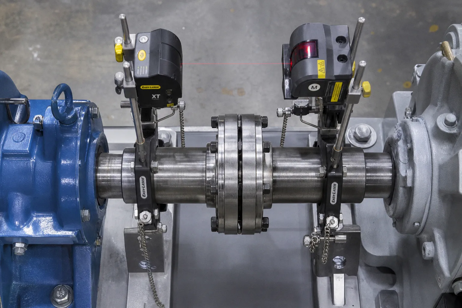
Laser systems simplify the geometry by measuring the relative position of the shafts and calculating correction values at the machine feet. They can display vertical and horizontal offset, angularity, soft-foot readings, thermal-growth targets, and the movement required at each foot.
The benefit is not that a laser makes alignment automatic. The benefit is that it reduces manual calculation and makes the relationship between measurement points and correction planes easier to manage. The system still has to be mounted correctly, the correct dimensions entered, and the readings checked for repeatability.
A laser setup can be compromised by:
- Brackets that move on the shaft or coupling.
- Incorrect distance entries.
- A beam interrupted by guards, piping, or reflective surfaces.
- Excessive ambient light or poor detector alignment.
- Shaft runout that has not been identified.
- A machine that cannot be rotated smoothly through the required measurement positions.
- Corrections made without checking the effect on the opposite plane.
Laser equipment also has operating limits and procedures that vary by manufacturer. The instrument manual governs the permitted rotation sequence, measurement arc, runout compensation, and allowable setup conditions. Unless a specific tool and procedure support an exception, the paired shafts should be rotated together. This is the normal basis for comparing the relative centerlines of the connected machines and for avoiding contamination from coupling runout.
The choice between laser and dial indicators should follow the equipment, the coupling, the access, and the competence of the crew. A laser used without dimensional discipline is not precision alignment. It is simply a more expensive source of bad numbers.
Decoding ANSI/ASA S2.75-2017 Alignment Quality Grades
ANSI/ASA S2.75-2017 provides a structured way to discuss alignment quality rather than relying on a single generic “good enough” number. Its approach considers operating speed and coupling characteristics, then associates the result with Alignment Quality Grades.
The grade concept is useful because alignment cannot be separated from the way a coupling flexes. A short flexible coupling, a spacer coupling, and a membrane or disk coupling respond differently to the same nominal offset. The distance between flexible elements changes the bending moment and the way loads reach the connected shafts and bearings.
The commonly used grades are presented as follows:
| Grade | General designation | Practical interpretation |
|---|---|---|
| AL4.5 | Minimal | A relatively loose quality level intended to avoid gross problems; it is not a sensible reliability target for a critical continuous-duty pump. |
| AL2.2 | Acceptable | A baseline quality level for many standard industrial applications when the equipment, coupling, and operating conditions support it. |
| AL1.2 | Excellent | A tighter quality level suited to demanding, high-speed, or critical-service equipment where reduced mechanical loading justifies the additional alignment effort. |
These grades should not be treated as universal permission to use one number on every pump. The practitioner still needs to identify the coupling type, rotational speed, machine dimensions, expected thermal growth, and the manufacturer’s requirements. A standard provides a framework; it does not eliminate engineering judgment.
The grade also belongs to the operating system, not just to the cold measurement. A pump may meet a cold alignment target and move outside that target after the driver reaches operating temperature. That movement may be caused by thermal growth, a temperature difference between the pump and driver, a distorted baseplate, or pipe forces that appear only after the process is established.
For this reason, a precision alignment report should make clear whether the recorded values are:
- Cold static alignment.
- Alignment after soft-foot correction.
- Alignment with piping connected.
- Alignment corrected for calculated thermal growth.
- Alignment verified after a period of operation.
- Alignment measured before or after the coupling guard and ancillary connections were installed.
Without that context, two apparently similar alignment results may describe different machines.
Critical Tolerance Thresholds for 1800 and 3600 RPM Systems
A laser alignment tolerance table is useful only when the reader knows what coupling configuration it applies to. The following values illustrate the tighter targets commonly associated with short flexible couplings and the higher-speed operating range. They should be checked against the current edition of the applicable standard, the coupling documentation, and the pump or driver manufacturer’s instructions before being used as a work specification.
Short flexible couplings
| Parameter | 1800 RPM — Acceptable | 1800 RPM — Excellent | 3600 RPM — Acceptable | 3600 RPM — Excellent |
|---|---|---|---|---|
| Offset | 3.0 mils | 2.0 mils | 1.5 mils | 1.0 mil |
| Angularity | 5.0 mils per 10 in | 3.0 mils per 10 in | 3.0 mils per 10 in | 2.0 mils per 10 in |
These values are not a promise that every pump meeting the table will run without vibration. They are alignment targets, not substitutes for a vibration baseline or a mechanical inspection. A machine with a bent shaft, damaged bearing, hydraulic imbalance, looseness, resonance, or a defective coupling can remain troublesome after alignment is corrected.
Speed is still central to the decision. A shaft rotating at 3,600 RPM completes twice as many revolutions per minute as one rotating at 1,800 RPM. The number of loading cycles increases accordingly, and dynamic behavior can become more sensitive to a small geometric error. The force does not follow one universal square-law rule for every coupling and shaft arrangement, so the safe conclusion is not that a given offset always creates a fixed multiple of force. The safe conclusion is that the same measured error deserves greater scrutiny as speed and criticality rise.
Spacer shaft and membrane couplings
Spacer and disk couplings require particular care because the flexible elements and the spacer length influence the bending moment. Their alignment requirements may be expressed per unit of spacer length or through coupling-specific angularity limits rather than by the same absolute offset numbers used for a short flexible coupling.
| Parameter | 1800 RPM — Acceptable | 1800 RPM — Excellent | 3600 RPM — Acceptable | 3600 RPM — Excellent |
|---|---|---|---|---|
| Offset, illustrative per-inch target | 1.0 mil/in | 0.6 mil/in | 0.5 mil/in | 0.3 mil/in |
The table is best treated as a reading aid, not as a universal specification. The actual coupling drawing may define limits at the flexible elements, at the shaft ends, or through a maximum angular displacement. A long spacer does not automatically make a large total offset acceptable. It changes the geometry through which the misalignment is converted into bending and reaction load.
This is also where the difference between coupling protection and machine protection becomes obvious. A coupling may tolerate a particular amount of offset without immediate rupture while still transmitting damaging loads to the pump and driver. The fact that an elastomer, grid, gear, or disk has not failed does not establish that the bearings and seal are lightly loaded.
The paired-rotation requirement
Both shafts should be rotated together during a conventional alignment measurement. The reason is practical: the technician is comparing the relative centerlines of two connected rotating elements. If only one shaft is turned, runout in the coupling bore, coupling face, shaft surface, or mounting bracket can enter the reading and appear as a false alignment error.
The usual procedure is to:
1. Remove or secure the coupling element as required by the equipment and measurement method.
2. Mount the indicators or laser heads rigidly.
3. Mark or identify repeatable angular positions.
4. Rotate the connected shafts together through the required measurement arc.
5. Record readings at the same positions on repeated passes.
6. Investigate any poor repeatability before moving the machine.
7. Apply corrections in small, controlled steps.
8. Repeat the full measurement after each significant correction.
A measurement that produces a large correction but cannot be repeated is not a difficult alignment; it is an unresolved measurement problem.
Eliminating Hidden Variables: Soft Foot and Pipe Strain
Alignment readings are only meaningful when the machines are sitting in a stable mechanical condition. Two conditions commonly invalidate an otherwise careful procedure: soft foot and pipe strain.
Soft foot
Soft foot occurs when a machine foot does not sit properly on the baseplate or mounting surface. Tightening the hold-down bolt pulls the frame into position, distorts the machine, and changes the shaft centerline. The machine can appear aligned with the bolts loose and move substantially when the bolts are torqued.
A movement of approximately 2 mils, or 50 micrometers, at a foot is commonly treated as a condition requiring correction in precision alignment work. The applicable project or equipment standard should govern the final acceptance value.
Soft foot can result from several different physical conditions:
- Bent foot: The foot is not flat, perhaps because of machining error, distortion, or impact damage.
- Twisted foot: The foot is not sitting parallel to the base, so bolt tension rotates or distorts the frame.
- Bowed foot: The foot or frame deforms as the bolt is tightened.
- Surface irregularity: Paint, rust, dirt, burrs, damaged shims, or an uneven base prevent proper contact.
- External loading: Piping, conduit, or other connected equipment pulls the machine and produces a reading that resembles soft foot.
The correction is not simply “tighten the bolt harder.” Depending on the cause, the solution may involve cleaning and deburring the surfaces, replacing damaged shims, machining a foot, correcting a baseplate, or using a properly fitted shim pack. Shims should be clean, flat, and large enough to support the foot without creating a flexible stack.
A practical soft-foot sequence is:
1. Torque the remaining hold-down bolts while leaving the test foot secured according to the procedure.
2. Loosen one foot at a time.
3. Measure the resulting movement with a dial indicator or laser system.
4. Record the direction as well as the magnitude of movement.
5. Correct the physical cause and install the required shim.
6. Retorque the foot and repeat the measurement.
7. Check every foot again after the first corrections are made.
Do not begin final shaft alignment while the machine is still being bent into place by its hold-down bolts. Otherwise, the alignment calculation is being made against a moving reference.
Pipe strain
Pipe strain is external force imposed on the pump casing by connected piping. It can be present even when the pump and driver were aligned correctly before the flanges were connected.
The effect may be visible immediately after bolting up, or it may develop when the process reaches temperature. Typical causes include:
- Pipe supports set at the wrong elevation.
- A pipe run that is too rigid near the pump nozzle.
- Thermal expansion that has no suitable flexibility.
- A vertical pipe imposing a bending moment through its weight.
- Misplaced guides, anchors, or spring supports.
- A flange mismatch that forces the piping into position.
- Settlement or movement elsewhere in the pipe rack.
The verification sequence should establish alignment with the piping in the intended mechanical condition, then compare it with the connected condition:
1. Establish the pump and driver alignment before final pipe connection, where the installation procedure permits.
2. Connect the piping without using the flange bolts to pull the pipe into place.
3. Confirm that supports, guides, and anchors are installed as designed.
4. Recheck alignment after the piping is connected.
5. If the alignment changes materially, correct the piping or support arrangement.
6. For hot services, account for the expected operating temperature and thermal movement.
7. Confirm that the pump nozzle loads remain within the applicable equipment and project limits.
The correction should not be to move the driver until the pipe happens to stop pulling the pump. That merely hides the external load in the cold alignment. When the process changes temperature, the force may change direction or magnitude and the pump will no longer be operating at the condition used for the correction.
API 610 is a standard for centrifugal pumps used in petroleum, petrochemical, and natural gas industry services. It includes requirements relevant to pump construction and installation interfaces, including nozzle loading considerations, but it is not a blanket alignment standard for every ANSI process pump. The applicable pump specification, piping design basis, contract requirements, and manufacturer documentation must be considered together.
The Risks of Relying on Coupling Manufacturer Limits
The most common conceptual mistake in alignment work is treating the coupling manufacturer’s maximum allowable misalignment as the target for the entire pump train.
The coupling drawing is usually answering a narrow question: how much offset or angularity can the coupling element accommodate without losing its intended function or suffering premature mechanical damage? That is important information, but it is not necessarily the amount of misalignment the pump bearings, mechanical seal, shaft, or motor can tolerate in continuous operation.
A flexible coupling is designed to accommodate some movement. It is not designed to turn a poorly aligned pump into a well-aligned one. When the coupling operates near its maximum deflection, it can impose additional reaction forces even if the element itself remains intact. An elastomer may heat and deteriorate. A grid may wear. Gear teeth may develop abnormal contact. Disk or membrane elements may experience alternating stress. The bearings and seal may show the consequences before the coupling fails visibly.
The correct order of priority is:
1. Start with the pump, driver, bearing, seal, and coupling manufacturer requirements.
2. Identify the applicable alignment standard and quality grade.
3. Account for rotational speed and coupling geometry.
4. Establish the cold alignment target, including thermal-growth compensation where required.
5. Correct soft foot and pipe strain before accepting the final result.
6. Verify the measurement through repeatable paired-shaft rotation.
7. Confirm the running condition through vibration, temperature, and operational checks.
The coupling manufacturer’s limit may be used as a maximum boundary. It should not automatically become the work-order acceptance target.
What vibration can and cannot tell you
Vibration is an essential confirmation tool, but it is not a replacement for alignment measurement. A pump can show acceptable overall vibration while a developing alignment problem is damaging a seal or bearing. Conversely, high vibration after an alignment correction does not prove that the alignment remains wrong.
Common pump shaft misalignment symptoms include:
- A strong running-speed component or an increase at running speed after coupling installation.
- Elevated axial vibration, especially when angular misalignment is present.
- Coupling element wear, cracking, powdering, or abnormal temperature.
- Repeated mechanical-seal leakage without a clear process or seal-material cause.
- Bearing temperatures that rise after the driver is moved or piping is connected.
- A motor that shifts during operation or shows looseness at the feet.
- Alignment readings that change significantly when hold-down bolts are torqued.
- A machine that is acceptable cold but becomes unstable at operating temperature.
These symptoms are not exclusive to misalignment. Hydraulic instability, imbalance, resonance, looseness, bent shafts, bearing damage, cavitation, and electrical problems can produce similar observations. The useful approach is to compare the evidence: alignment data, vibration spectrum, phase, bearing temperature, coupling condition, process state, and maintenance history.
For example, a high running-speed component combined with repeatable alignment movement during coupling installation points toward a mechanical alignment issue. A broadband increase with hydraulic noise and fluctuating flow may point elsewhere. A seal leak with no corresponding change in vibration may require inspection of seal installation, flush conditions, shaft runout, or process chemistry rather than another round of shimming.
Thermal growth and operating alignment
The final alignment target is often intentionally offset in the cold state so that the pump and driver approach a better relationship at operating temperature. The required correction depends on the equipment materials, support arrangement, temperature difference, shaft elevation, and the manufacturer’s thermal-growth data.
Thermal growth should not be guessed from a generic value copied from another pump. The temperature at the bearing housing is not necessarily the temperature of the shaft centerline, and the pump casing may grow differently from the motor frame. A vertical or horizontal offset may change as the machine heats, while angularity can change if the supports do not behave symmetrically.
A reliable procedure records the basis for the thermal target:
- Which machine is expected to move?
- From which reference temperature?
- In which direction?
- By how much?
- Is the value calculated, measured from operating history, or supplied by the manufacturer?
- Does the target apply to the pump, the driver, or the coupling centerline?
Where the service is critical, a hot verification or post-startup review can show whether the cold target was appropriate. If the operating data contradict the prediction, the answer is not to edit the report. The equipment, supports, temperatures, and calculation assumptions need to be reviewed.
Making the Procedure Repeatable
Precision alignment succeeds when it becomes a controlled process rather than an individual technician’s preferred technique. The written pump shaft alignment procedure should define the machine condition, measurement method, acceptance criteria, and evidence required to close the job.
At minimum, the procedure should address:
- Lockout, guarding, coupling removal, and safe rotation.
- Baseplate condition and grout integrity.
- Shaft and coupling cleanliness.
- Runout checks where the geometry or history requires them.
- Soft-foot measurement and correction.
- Pipe-support and flange condition.
- Thermal-growth targets.
- Instrument calibration and setup verification.
- Paired-shaft rotation.
- Horizontal and vertical correction sequence.
- Final torque values.
- Repeat measurement after torquing.
- Coupling installation and guard clearance.
- Baseline vibration and temperature readings after startup.
The correction itself should be deliberate. Large shim changes can introduce new errors, while moving a motor horizontally with excessive force can damage jacking screws or shift the machine unpredictably. After a vertical correction, the technician should recheck horizontal alignment and vice versa. After final bolt torque, the machine should be measured again because the act of tightening can change the result.
A useful alignment record includes the raw readings, not just the final green status on a laser screen. It should show the machine dimensions entered into the instrument, the soft-foot values, the thermal target, the final offset and angularity, the shim changes, and the condition of the piping. That record makes the next failure investigation faster and helps distinguish a new problem from a recurring installation defect.
The Risks of “Zero Vibration” as a Literal Target
The title of a precision alignment program may promise zero vibration, but a running pump will never be mechanically silent. Hydraulic forces, rolling elements, electrical excitation, structural response, and process conditions all contribute to the measured signal.
“Zero vibration” is better understood as a direction: remove the vibration caused by avoidable mechanical error, then establish a stable baseline for the remaining forces. The target is a pump train that does not add unnecessary loading through misalignment, soft foot, pipe strain, looseness, or coupling installation.
That distinction protects the maintenance team from two opposite mistakes. The first is accepting poor alignment because the pump is still running. The second is moving the machine repeatedly in search of an impossible instrument reading while the actual cause is cavitation, resonance, imbalance, or a damaged bearing.
A good commissioning decision combines the measurements:
- Alignment meets the equipment-specific target.
- Soft foot is corrected and remains stable after final torque.
- Pipe connection does not pull the pump out of alignment.
- Coupling assembly and guard clearances are correct.
- Vibration is consistent with the machine’s baseline and service condition.
- Bearing temperatures stabilize rather than continuing to rise.
- Seal performance is normal for the process and seal design.
- Operating data remains repeatable after load or temperature changes.
Final Position
A pump shaft alignment tolerance guide is valuable only when it moves the conversation away from coupling survival and toward machine reliability. The coupling is one part of the train. Its published limit may prevent immediate damage to the coupling element, but it does not establish a safe long-term load for the pump bearings, seal, shaft, or motor.
The practical roadmap is therefore straightforward, even if the work is not: choose a tolerance appropriate to speed and coupling geometry; use a measurement method that the crew can set up and repeat correctly; rotate the paired shafts together unless the specific instrument procedure provides another validated method; eliminate soft foot; control pipe strain; account for thermal growth; and verify the result after the machine is assembled and operating.
Alignment is not finished when the laser screen turns green. It is finished when the machine remains mechanically stable under the loads it was built to carry.