Laser shaft alignment vs dial indicator: choosing the right method
A pump can leave the workshop perfectly serviceable and still begin a shift with the wrong alignment.
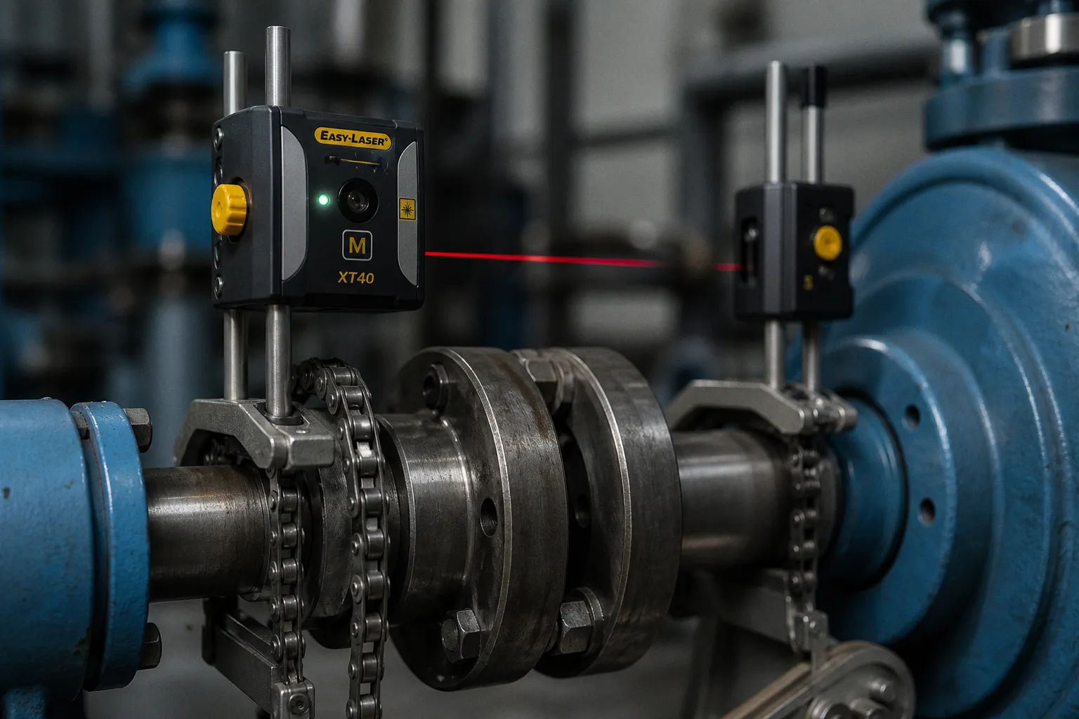
The usual culprit is not a dramatic installation mistake; it is a small offset at the coupling, a soft foot under the motor, a bracket that flexes under its own weight, or a thermal growth difference that only appears after the machine reaches operating temperature. On the ground, those fractions of a millimeter become vibration, seal leakage, bearing heat, coupling wear, and another unplanned stop.
Compare car rental deals in United Kingdom
See available offersPartner link — DiscoverCars comparisonThat is why the choice between laser shaft alignment and dial indicator methods is not simply a question of old tools versus new tools. Both methods can produce a reliable alignment when the technician understands the mechanics and works within the equipment manufacturer’s tolerances. The difference lies in how much of the calculation, error control, documentation, and awkward physical work the method places on the person standing beside the machine.
We can think of it this way: a dial indicator gives an experienced technician a precise instrument and a set of measurements to interpret, while a modern dual-laser system turns much of that interpretation into a guided workflow. The right choice depends on the criticality of the pump, the available rotation, the operating temperature, the skill on the maintenance team, and how often the alignment task has to be repeated.
The physics of precision: what each method is really measuring
Shaft alignment is usually described in terms of two errors:
- Offset, where the centerlines of the driver and driven machine are parallel but displaced.
- Angular misalignment, where the centerlines meet at an angle rather than remaining parallel.
A dial indicator measures the relative movement between a reference shaft and the machine being adjusted. In a rim-and-face setup, one indicator measures radial movement around the coupling and another measures axial movement across its face. The technician rotates the shaft, records the readings, corrects for bracket sag and geometric relationships, and then calculates the required horizontal and vertical movement at the machine feet.
That process is entirely capable of producing high-quality results. Under ideal conditions, dial indicators can achieve accuracy around 0.01 mm. A skilled technician who understands the indicator setup, takes repeatable readings, and correctly compensates for bracket sag can align a pump to the manufacturer’s tolerance without any digital equipment.
The difficulty is that the tool does not explain the machine to you. It provides readings, not a conclusion. You have to know whether a reading comes from actual misalignment, shaft runout, coupling hub runout, a loose foot, a moving bracket, or an inconsistent rotation. If the setup is mechanically unstable, a very fine indicator can simply report a very precise version of a bad measurement.
A dual-laser system approaches the same problem with two sensors mounted on the shafts or coupling hubs. As the shafts rotate, the system calculates the relative centerlines and presents the correction values at the machine feet. Modern systems can measure misalignment down to approximately 0.001 mm, or 0.0001 inches, although the practical result still depends on setup quality, machine condition, environmental factors, and the tolerance being applied.
The key distinction is not that lasers are magically more accurate in every situation. It is that they reduce the number of manual calculations and make the relationship between measurement and correction easier to follow. That matters when operator fatigue is already high, the pump is installed in a cramped bay, or the person performing the work does not align rotating equipment every day.
A laser system does not replace mechanical judgment; it gives that judgment better feedback, faster calculations, and a clearer record of what changed.
For critical high-speed machinery, the repeatability and digital reporting of a laser system often make it the practical standard. For a smaller pump in a less demanding service, a dial indicator may remain the more sensible tool, particularly when a capable technician already has the fixtures and knows the machine family well.
Accuracy on paper versus accuracy on the ground
The comparison below describes the method under competent working conditions, not a poorly mounted laser against a carefully executed dial-indicator setup.
| Parameter | Dial indicator alignment | Laser shaft alignment |
|---|---|---|
| Typical measurement capability | About 0.01 mm under ideal conditions | Modern systems may measure down to about 0.001 mm |
| Shaft rotation | Usually 180 to 360 degrees | Some systems can calculate with roughly 40 degrees of rotation |
| Main calculation burden | Technician calculates and interprets readings | System calculates offsets and foot corrections |
| Bracket sag | Must be measured and compensated manually | Reduced by sensor geometry, but setup errors still matter |
| Thermal growth | Calculated and entered manually | Cold offsets can be entered into the system |
| Documentation | Readings recorded by hand or separately | Digital reports and saved measurement records |
| Purchase cost | Relatively low if indicators and fixtures are already available | Approximately $15,000–$25,000 for a system |
| Best fit | Skilled technicians, routine equipment, low capital budget | Critical machinery, repeated work, limited rotation, traceable reporting |
The practical question is therefore less “Which tool has the smallest stated resolution?” and more “Which method gives this team the most trustworthy result under this machine’s actual constraints?”
Rotation, access, and the bracket-sag problem
The first physical constraint we encounter during alignment is often not the instrument. It is the coupling guard, the wall behind the motor, the pipework above the pump, or a shaft that simply cannot be turned freely.
Traditional dial-indicator methods generally require the shaft to rotate through 180 to 360 degrees. That rotation allows the technician to collect enough readings to calculate the angular and offset relationships. If the coupling is stiff, the pump is partially seized, or the available clearance permits only a small movement, the job becomes slower and the measurement uncertainty rises.
Laser systems can often calculate alignment with as little as 40 degrees of shaft rotation. That does not mean we can ignore the condition of the rotating assembly, and it does not mean every installation should be measured with the smallest possible sweep. It does mean that a physically restricted machine is less likely to force us into unsafe disassembly or improvised measurement practices.
A short rotation range is especially useful when:
1. The coupling sits close to a guard or structural member.
2. The motor and pump cannot be uncoupled without disturbing pipe strain or other services.
3. The machine has a heavy or high-inertia rotor.
4. A shutdown window is short and repeated full rotations would consume most of the available time.
5. The equipment is installed in a narrow skid where a technician cannot maintain a comfortable working position.
This is where tactile feedback still matters. When you turn a shaft by hand, you feel roughness, tight spots, and uneven resistance. A digital system may calculate a result quickly, but the person at the coupling still needs to notice whether the machine is behaving like a healthy rotating assembly. On the ground, the best alignment workflow combines the instrument’s calculation with the technician’s hands and ears.
Why bracket sag can invalidate a good measurement
Bracket sag, also called bar sag, is the deflection caused by gravity bending the indicator bracket or support bar. The indicator may be perfectly calibrated, yet the bracket itself changes position as it moves around the shaft. Over an 8-inch coupling span, a typical sag error can be approximately 8 to 10 mils, or 0.2 to 0.25 mm. That is large enough to overwhelm the alignment tolerance on many pump installations.
The correction is not complicated, but it must be performed. The technician mounts the bracket on a rigid reference, takes readings at known positions, determines how much the bar deflects, and applies that value to the alignment calculations. The exact procedure depends on the fixture and measurement arrangement.
If the bracket sag is ignored, the machine may be moved in the wrong direction. The final indicator reading can look neat because the same error has followed the setup through the calculation, but the shafts will not necessarily be collinear when the coupling is assembled.
Laser systems reduce this particular source of error because the sensor arrangement and software account for the geometry more directly. That is a meaningful laser alignment benefit for industrial pumps, but it is not a license to mount the sensors casually. Loose brackets, dirty coupling hubs, magnetic movement, sensor misidentification, and incorrect dimensions can still produce an unreliable result.
A useful rule is simple:
- If the technician cannot explain how the measurement setup is referenced, the result is not yet trustworthy.
- If a laser system gives a result that conflicts sharply with the mechanical condition of the machine, stop and investigate rather than accepting the screen automatically.
Thermal growth: the alignment that changes after startup
Cold alignment is only a starting condition. Once the pump and driver operate, their temperatures rise at different rates and their materials expand over different distances. A motor may lift relative to the pump, or the pump casing and connected piping may shift the driven shaft centerline. If we align the machine cold and do not account for that movement, the shafts can become misaligned exactly when the process needs them most.
When pump operating temperatures exceed approximately 200°F, or 93°C, hot alignment compensation or a pre-calculated cold offset is required. The threshold is a practical warning point rather than a universal answer for every machine. The actual correction depends on temperature change, material, geometry, and the vertical distance over which expansion occurs.
The basic relationship is:
TG = T × L × C
Here, T is the temperature change, L is the relevant length or height, and C is the material’s coefficient of thermal expansion. The formula is straightforward; the difficult part is selecting realistic temperatures and dimensions. A single generic offset cannot be applied to every pump because a stainless-steel pump, a cast-iron base, a carbon-steel motor frame, and a long elevated shaft line will not respond in the same way.
With dial indicators, we generally calculate the thermal offset separately and enter the required cold correction into the alignment worksheet. The technician then positions the machine low or high by the calculated amount so that thermal growth brings it toward the correct operating alignment.
With a laser system, the cold offset can be entered into the instrument. The software then includes the thermal target when it calculates the required foot corrections. This is one of the clearest differences in day-to-day usability: the laser does not eliminate the engineering calculation, but it gives us a reliable place to store and apply it without carrying a separate set of handwritten corrections through every adjustment.
If the machine trips after reaching operating temperature, we can also perform a hot alignment verification. The useful post-trip window is approximately 120 to 180 minutes, before the equipment cools enough for the thermal-growth data to lose its meaning. The timing matters. A reading taken too late may describe a partly cooled machine rather than the condition that existed during operation.
The sequence should be deliberate:
1. Record operating temperatures and the machine’s running condition before shutdown where possible.
2. After the trip, secure the equipment and follow the site’s isolation procedure.
3. Take the hot alignment readings within the available thermal window.
4. Compare the measured movement with the predicted thermal offset.
5. Correct the cold target or investigate other causes if the movement is substantially different.
If the thermal result does not match the calculation, we do not simply increase the offset until the numbers look comfortable. The discrepancy may point to pipe strain, a loose base, an unstable foundation, incorrect temperature assumptions, or a machine that is moving in a direction the original model did not include.
Pre-alignment work: the checks no instrument can skip
The most expensive alignment error is often made before the indicator or laser is mounted. A laser system cannot correct a bent base, a distorted coupling hub, or a motor foot that is not sitting flat. It will measure the geometry presented to it, and the machine may still move when the bolts are tightened.
Soft foot
Soft foot describes a condition where one or more machine feet do not sit firmly on the base before the hold-down bolts are tightened. When the bolt is tightened, the motor frame pulls down or twists. The alignment changes during the very act of securing the correction.
For many pump installations, the soft foot gap under each foot should be less than 0.05 mm, or 0.002 inches. We check this condition by loosening and tightening the relevant foot while measuring movement, then correcting it with suitable shims or by addressing the base and foot surfaces.
A machine with soft foot can produce confusing alignment results:
- The readings change after every bolt-tightening sequence.
- The horizontal and vertical corrections appear to fight each other.
- The final result is acceptable with loose bolts but fails when the machine is secured.
- Vibration returns soon after commissioning even though the initial alignment report looked good.
If you see that pattern, changing the alignment method will not solve the root problem. The foot must be corrected first.
Coupling hub runout
The coupling hubs also need a clean mechanical check. Both outside diameter and face runout should generally be below 0.05 mm, or 0.002 inches TIR, before they are used as the reference for alignment.
Runout can come from a damaged hub, contamination between the hub and shaft, a bent shaft, incorrect mounting, or a measurement surface that has been marked by previous work. A laser may make the reading process faster, but it still relies on the sensors being mounted to a surface that represents the shaft centerline accurately.
We also look at the base, shims, shaft condition, coupling condition, and piping. The pump should not be treated as an isolated object if the connected pipework is pulling it sideways or vertically. On the factory floor, alignment is a system condition, not merely a number displayed beside the coupling.
A practical pre-alignment sequence
Before choosing between dial indicators and lasers, we use the same mechanical sequence:
1. Lock out and isolate the equipment, then confirm that the shaft can be turned safely.
2. Inspect the base and hold-down hardware for looseness, corrosion, damaged threads, or distorted mounting surfaces.
3. Check soft foot and correct it before taking final alignment readings.
4. Clean the shaft and coupling hubs, removing rust, oil film, paint, and raised burrs.
5. Measure hub runout on the outside diameter and face.
6. Inspect the coupling for wear, cracks, incorrect gap, and signs of angular overload.
7. Check for pipe strain and confirm that the pump casing is not being pulled out of position when connected.
8. Choose the measurement method based on access, rotation, tolerance, temperature, and available skill.
9. Perform rough alignment before taking precision readings.
10. Tighten and recheck, because every adjustment can change the geometry elsewhere.
This sequence is where many alignment programs either become dependable or remain a cycle of repeat failures. The instrument is only one stage in the work.
Choosing the method for the machine, not the marketing brochure
The strongest case for dial indicators is not nostalgia. It is control. A competent technician can use a relatively affordable set of instruments, work without proprietary software, and understand each number from first principles. Dial indicators are particularly practical when the maintenance team already performs this work frequently and the machines have generous access for rotation.
They also make economic sense for occasional installations. A new laser system can cost approximately $15,000 to $25,000, while hiring a specialist laser alignment contractor may cost around $800 to $1,500 per job. For a site that needs one precision alignment every few years, outsourcing may be more rational than purchasing, calibrating, storing, and training people on a system that spends most of its life in a cabinet.
Lasers become more compelling as the consequences of misalignment rise. High-speed pumps, critical process trains, machines with narrow tolerances, and equipment located in difficult access areas benefit from faster rotation requirements, guided corrections, thermal-growth inputs, and digital reporting. A saved alignment record also helps us compare the machine over time instead of treating every service visit as an isolated event.
Here is the decision in operational terms:
| Site condition | Usually the stronger choice | Why |
|---|---|---|
| A skilled alignment technician is available | Either method | Skill and setup quality may matter more than instrument type |
| Shaft rotation is restricted | Laser | Measurements may be possible with a much smaller rotation |
| The pump is critical to production | Laser or specialist contractor | Faster verification, thermal compensation, and traceable reporting |
| Work is infrequent and budget is limited | Dial indicator or outsourced laser service | Lower capital commitment |
| Operating temperature is high | Laser with thermal input, or a disciplined dial method | Thermal offsets can be managed clearly and repeated |
| Many similar pumps require routine service | Laser | The time savings and records accumulate across the fleet |
| No reliable pre-alignment process exists | Neither method alone | Soft foot, runout, pipe strain, and base condition must be corrected first |
The calculation should include more than the purchase price. We look at lost production, contractor availability, repeat callouts, seal and bearing consumption, training time, and the cost of an alignment that must be redone during the next shutdown. A laser system may pay for itself through avoided rework on a busy site, but that is a site-specific business case, not a guaranteed percentage of energy or maintenance savings.
How alignment affects pump reliability and energy use
Misalignment increases the mechanical load carried by the coupling, bearings, seals, and shaft. It can also make vibration troubleshooting unnecessarily difficult because the symptoms overlap with imbalance, looseness, cavitation, resonance, and bearing damage.
When we see elevated vibration after a pump overhaul, alignment is one part of a wider diagnostic path. We do not assume every vibration problem is an alignment problem. We compare readings at the pump and motor bearings, examine axial and radial patterns, review operating conditions, and look for changes after coupling correction. If the pump is cavitating or running away from its best efficiency point, perfect shaft alignment will not remove the hydraulic cause.
Energy efficiency deserves the same caution. Poor alignment can contribute to mechanical losses and premature component wear, but there is no universal energy-saving percentage that applies to every industrial pump. Speed, impeller condition, fluid viscosity, hydraulic duty, bearing condition, and control strategy may have a much larger effect. A good alignment supports efficient operation; it does not turn an incorrectly selected pump into an efficient one.
The broader maintenance benefit is often more predictable: stable alignment reduces one source of avoidable stress and gives the condition-monitoring team cleaner data. When the mechanical geometry is controlled, vibration trends become easier to interpret, and a change in the spectrum is more likely to point toward a developing fault rather than an alignment problem left over from the last shutdown.
For teams building a repeatable maintenance program, alignment records should sit alongside vibration readings, seal history, bearing replacements, operating temperatures, and work-order notes. That creates the real-world context needed to distinguish a one-time installation error from a machine that is gradually moving on its base.
A field decision: when to use each method
We can make the final choice through a few practical if-then questions.
If the shaft can rotate freely, the machine is accessible, and the technician is highly experienced with indicators, then dial indicator alignment remains a sound method. The result can meet the required tolerance, provided bracket sag, runout, soft foot, and thermal growth are handled correctly.
If the shaft can only be rotated through a small angle, then a laser system is usually the better route. The shorter rotation requirement reduces physical struggle and can make the difference between a controlled measurement and an improvised one.
If the pump operates above approximately 93°C, then build thermal growth into the alignment target rather than treating hot movement as a surprise. A laser system makes the data easier to apply, but a dial-indicator process can also work when the calculations and temperature assumptions are documented.
If the machine is production-critical and a failed pump carries a high cost, then use a laser system or bring in a specialist contractor. The value comes from repeatability, speed, reporting, and a lower chance that a calculation or bracket-sag correction is lost during a rushed shutdown.
If the machine has soft foot or excessive hub runout, then stop the alignment process and correct those conditions first. No instrument can make an unstable mechanical reference reliable.
If the team is comparing tools only by advertised resolution, then step back and compare the whole workflow. Measurement range, setup time, technician skill, thermal compensation, documentation, calibration, and post-alignment verification all affect the result.
One useful extension of the broader troubleshooting process is a structured look at common causes of rotating equipment failure, provided it is used as a starting point rather than a substitute for measurements on the machine itself.
The method that protects the person doing the work
Alignment is often discussed as though the only outcome is a number: offset within tolerance, angularity within tolerance, job complete. But the person performing the work has to hold a fixture in an awkward position, rotate a shaft repeatedly, read small graduations through a crowded coupling area, and make adjustments while the shutdown clock is running.
That human factor changes the engineering decision. Operator fatigue is not an abstract concern. Fatigue makes a technician more likely to skip a repeat reading, accept a loose bracket, overlook a damaged shim, or tighten one foot without checking how the opposite foot moved. A method that reduces unnecessary rotation and makes the correction path visible can improve the quality of the work because it gives the technician more attention for the mechanical details that still require judgment.
Laser alignment is often the better experience in this environment, especially when the system guides the technician through dimensions, rotation, target values, and foot corrections. The tactile feedback remains with the operator: the feel of the shaft, the resistance of the adjustment bolts, the condition of the shims, and the movement of the motor as the correction is applied. The screen should support that judgment, not replace it.
Dial indicators, in contrast, can teach the geometry very directly. They are valuable training tools because they force the technician to understand how a reading at the coupling becomes a correction at the feet. On a mature maintenance team, that knowledge is a strength. On a team with limited alignment experience, the same openness can create more opportunities for calculation and setup errors.
The decision in plain terms
For most plants, the answer is not to discard dial indicators and purchase lasers for every pump. It is to match the method to the consequence of failure and the conditions of the job.
Choose dial indicators when the equipment is accessible, the rotation is practical, the tolerance is understood, and the technician has the experience to compensate for bracket sag and thermal movement. Choose laser shaft alignment when the machinery is critical, the access is poor, the rotation is restricted, the alignment must be documented, or the site performs enough work to justify the capital investment. When the task is occasional but high consequence, a qualified alignment contractor can provide the laser capability without turning it into an idle asset.
The strongest maintenance programs use both methods without treating either as a shortcut. They begin with soft foot, runout, base condition, coupling condition, and pipe strain. They define the operating target, account for thermal growth, make the correction, tighten and remeasure, then verify the machine after it returns to service.
That is the real measure of precision: not the smallest number printed on an instrument, but a pump that runs quietly, holds its seal, protects its bearings, and does not ask the operator to repeat the same alignment job on the next shift.