Pump soft foot correction: a step-by-step field guide
A pump foot that lifts by more than 0.05 mm when its bolt is loosened is outside the commonly accepted soft foot tolerance. The shaft may still be aligned at that moment. The machine is not mechanically stable.
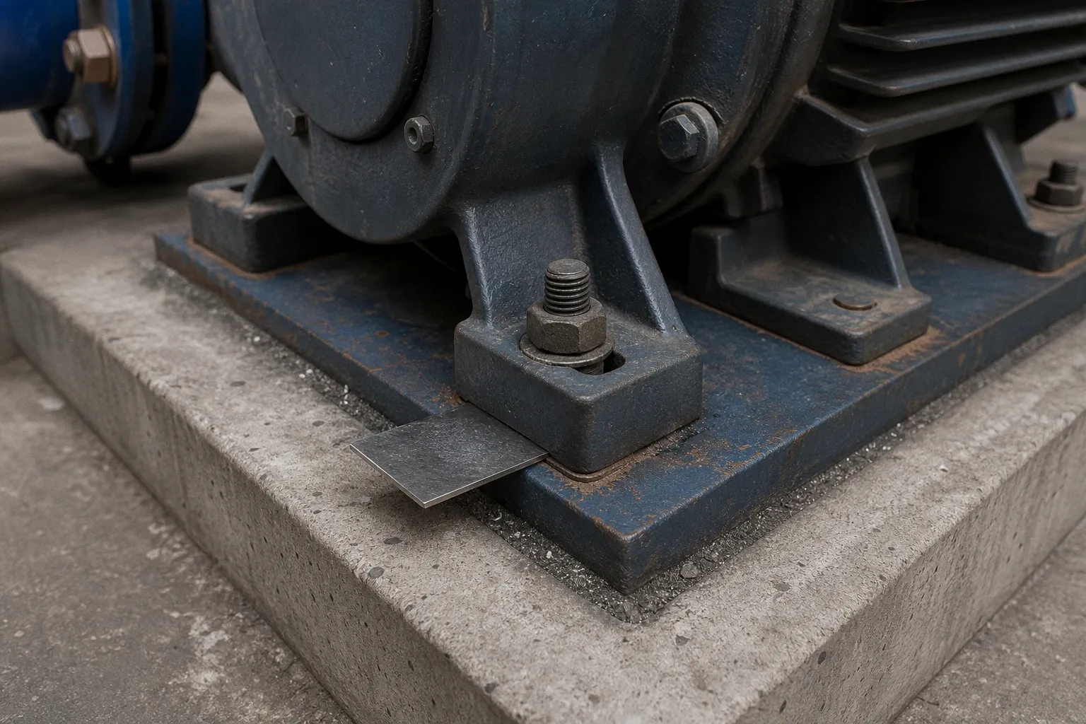
That distinction matters. Final pump shaft alignment performed over a distorted base produces a temporary result. Once the foot bolt is tightened, the frame moves. Coupling offset changes. Bearing loads increase. Vibration appears after startup rather than during the alignment procedure. The error is then misclassified as a coupling, bearing, or hydraulic problem.
Pump soft foot correction steps are therefore a precondition for alignment, not an optional finishing operation. The sequence is direct:
1. Isolate the machine and release external forces.
2. Measure foot movement with one bolt loosened at a time.
3. Classify the distortion.
4. Correct the contact condition with controlled shimming or machining.
5. Retorque the feet in a repeatable sequence.
6. Repeat the measurement.
7. Perform final shaft alignment only after the soft foot result is within tolerance.
The target is typically 0.002 in. (0.05 mm) or less. Some industrial practices allow 0.003 in. (0.076 mm). The lower value is the better control limit when the pump, motor, bearings, or coupling have low tolerance for movement.
Why soft foot invalidates pump alignment
Soft foot is a condition in which one or more machine feet do not make stable, full-area contact with the base before the foot bolts are tightened. The bolt pulls the foot down. That force deforms the machine frame or casing.
The machine appears fixed only because the bolt is acting as a structural clamp. Remove or loosen the clamp, and the foot rises. Tighten it again, and the machine returns to a different position. This creates alignment latency between the measured state and the operating state: the shaft was aligned in one geometry, then forced into another.
The effects extend beyond coupling alignment:
- Bearing housings can shift relative to the shaft centerline.
- Pump casing distortion can alter internal clearances.
- Mechanical seal faces can lose their intended relationship.
- Coupling alignment readings can change between measurement passes.
- Vibration levels can increase at running speed.
- Foot bolts can lose preload through repeated movement.
- The operator may compensate for the distortion by moving the machine, creating a second error.
Soft foot is common after equipment installation, baseplate repair, repainting, corrosion, repeated maintenance, or pipework modification. It can also be induced by connected piping. In that case, the pump may have acceptable contact when disconnected and fail the pump soft foot check after the pipe flange is brought into position.
A shaft alignment result is not valid if the machine frame changes when the foot bolts are tightened.
The diagnostic sequence must separate local foot distortion from external loads. Otherwise, technicians correct the symptom at the foot while the piping, baseplate, or foundation continues to apply force.
Diagnosing the four primary types of soft foot
The practical classification contains four main types. Each requires a different correction logic. Treating all gaps as a simple shim requirement produces high shim counts, poor contact, and repeat failures.
Parallel soft foot
Parallel soft foot produces a relatively uniform gap between the machine foot and the base. The foot is not seated across its contact area. The gap may result from an incorrect base elevation, a machining error, a deformed foot, or a shim stack that does not match the actual surface.
The measurement is usually consistent across the foot. A feeler gauge can identify the gap. A dial indicator or laser alignment system can quantify vertical movement when the bolt is loosened.
Correction is normally straightforward if the surfaces are sound:
- Clean the base and foot.
- Remove loose rust, paint, scale, oil, and debris.
- Measure the gap at multiple points.
- Select shims that cover the contact area.
- Tighten the foot bolt.
- Recheck the movement.
Uniformity is the diagnostic signal. If the gap varies substantially from one side of the foot to another, the condition is more likely angular soft foot.
Angular soft foot
Angular soft foot creates a wedge-shaped gap. One edge of the foot contacts the base while the opposite edge remains open. The foot may look seated from above, but the contact is incomplete.
This condition cannot be corrected reliably by inserting one flat shim of uniform thickness. The shim must match the angle or be built as a controlled step-shim arrangement. Measure the gap at the front, back, and sides of the foot. The purpose is to establish the profile rather than to estimate a single average value.
Step-shimming is an accepted method when the gap is within practical limits. The available guidance limits the arrangement to a maximum of five steps and approximately 0.015 in. (0.38 mm) total gap variation. The steps must be stable and must not create unsupported regions beneath the foot.
If the angle is severe, the correct repair is machining or restoration of the foot and base surface. A large stack of thin shims is not a substitute for correcting a damaged interface.
Squishy soft foot
Squishy soft foot is caused by an unstable interface. Typical causes include:
- Dirt or corrosion trapped under the foot.
- Too many shims.
- Shims with poor flatness.
- Shims that do not cover enough of the foot.
- A damaged base surface.
- Loose, folded, or contaminated shim material.
The foot may show inconsistent movement during repeated bolt loosening and tightening. Readings drift. The machine does not return to the same position. This increases measurement noise and raises alignment error.
The usual control is to clean the interface and reduce the shim count. A stack should normally contain no more than four or five shims beneath one foot. The three thinnest shims in the stack should have a combined thickness of at least 0.010 in. (0.25 mm), according to common shimming guidance. The purpose is not to maximize thickness. It is to prevent a fragile stack of thin material from behaving like a spring.
Each shim should cover at least 80% of the machine foot contact area. A narrow shim placed directly under the bolt may support preload locally while leaving the rest of the foot unsupported. That is not a stable correction.
Induced soft foot
Induced soft foot is created by an external force. Pipe strain is the most common example in pump installations. Other causes include connected ducting, cable trays, rigid guards, expansion loads, baseplate distortion, or a machine mounted against another component.
The pump may pass a soft foot test with the piping disconnected and fail after the flange bolts are tightened. This is not a contradiction. The mechanical boundary condition has changed.
The diagnostic method is comparative:
1. Measure the feet with the external connection released.
2. Restore the connection without forcing the flange into position.
3. Repeat the foot measurement.
4. Compare vertical movement and alignment change.
5. Locate the external force before adding shims.
Shimming an induced soft foot can mask the pipe strain temporarily. It does not remove the source. The installation must be corrected so the piping reaches the pump flange without using the pump casing as a lever.
Establishing the machinery alignment soft foot tolerance
The tolerance is based on vertical movement when a foot bolt is loosened. It is not based on visual contact, the number of shims installed, or whether the coupling can be rotated by hand.
A common industry limit is:
| Control point | Typical limit | Interpretation |
|---|---|---|
| Preferred soft foot limit | 0.002 in. (0.05 mm) | Suitable control target for precision alignment |
| Alternative field limit | 0.003 in. (0.076 mm) | Used in some industrial practices |
| Shim contact coverage | Minimum 80% of foot area | Reduces local loading and instability |
| Shim count per foot | Maximum 4–5 | Limits squishy foot behavior |
| Step-shim gap variation | Maximum 0.015 in. (0.38 mm) | Applies to controlled angular correction |
| Step-shim count | Maximum 5 steps | Prevents excessive discontinuity in support |
The lower tolerance should be used when the machine has high rotational speed, narrow bearing clearances, a rigid coupling, a sensitive mechanical seal, or a history of vibration-related failures. A tolerance is a control limit, not a prediction of acceptable operating performance. A pump can run below 0.003 in. and still have an alignment, hydraulic, or foundation problem.
Measurement repeatability is part of the result. If the first reading is 0.04 mm, the second is 0.09 mm, and the third is 0.02 mm under the same conditions, the interface is not under control. Clean the foot, verify the indicator setup, inspect the bolt and threads, and repeat the test.
Measurement setup
The pump and driver should be in the condition used for alignment. The coupling guard may be removed for access, but the machine must be isolated and secured. Do not use a running machine for a soft foot measurement.
Use one of two basic measurement arrangements:
- A dial indicator mounted to measure vertical movement at the foot or casing.
- A laser alignment system capable of identifying soft foot movement.
Laser tools improve measurement visibility and reduce manual reading error. They do not correct the foot. The correction still requires cleaning, shimming, surface repair, or machining.
The indicator position should be stable. Avoid mounting the reference on a loose guard, flexible cover, or component that moves with the foot. Record the foot location and measurement direction. This makes the second and third passes comparable.
Loosen one foot bolt at a time while observing the movement. Do not release all bolts simultaneously. That changes the machine geometry and removes the information needed to identify the unstable foot.
The pump soft foot correction procedure
The correction should follow a controlled sequence. The sequence prevents the technician from mixing the effects of contamination, bolt preload, pipe strain, and shaft movement.
1. Prepare the interface
Stop, isolate, and lock out the pump and driver. Remove the coupling guard if required for access. Verify that the machine cannot start and that stored energy is controlled.
Inspect every foot and the corresponding base area. Remove:
- Rust scale.
- Old paint films.
- Dirt and grease.
- Burrs around bolt holes.
- Loose grout or damaged shims.
- Foreign material trapped under the foot.
The cleaning step has high leverage. A small particle under a foot can create a gap larger than the entire allowable tolerance. Do not measure a contaminated interface and then design a precision shim correction around a temporary obstruction.
Check the foot bolts for damaged threads, distorted washers, bottoming, or insufficient engagement. A bolt that bottoms in the hole can generate apparent clamping force without securing the foot correctly.
2. Establish a baseline
Tighten the foot bolts in a consistent pattern. Use the manufacturer’s specified torque where available. Exact torque values cannot be generalized because they depend on bolt size, grade, lubrication, and manufacturer requirements.
Take a baseline alignment reading if the machine is already assembled. This provides a reference for how much the frame changes during correction. It is not the final alignment result.
Mark the feet. Use a fixed naming convention such as driver-side front, driver-side rear, pump-side front, and pump-side rear. Ambiguous foot labels create data errors during repeated measurements.
3. Loosen one bolt and record movement
Loosen one foot bolt while monitoring the indicator or soft foot function of the laser system. Record the upward movement. Retighten the bolt before moving to the next foot if the procedure requires the machine to remain in its original state.
Repeat for every foot. The largest movement identifies the primary soft foot location, but secondary feet may also be outside tolerance.
Do not classify a foot from one reading alone if the result is close to the limit. Repeat the measurement. A reading near 0.05 mm requires better control than a large, obvious gap. The objective is not to produce a favorable number. It is to establish whether the foot returns to a stable mechanical position.
4. Identify the distortion pattern
Use feeler gauges to measure the physical gap. Measure more than one point on each foot. For an angular foot, record front, rear, left, and right positions. The pattern determines the correction:
- Uniform gap: parallel soft foot.
- Wedge-shaped gap: angular soft foot.
- Variable or unstable gap: squishy foot, contamination, or damaged surfaces.
- Change after pipe connection: induced soft foot.
- Significant corrosion or deformation: machining or surface repair required.
Do not average the measurements and install a single shim based on that average. The average may conceal the actual contact geometry.
5. Correct a parallel or short foot
A short foot can occur diagonally. It is sometimes described as diagonal parallel soft foot. The correction method is controlled tightening of the two non-soft diagonal feet while leaving the soft feet loose.
Proceed as follows:
1. Identify the two diagonal feet that are not producing the soft foot condition.
2. Tighten only those two feet.
3. Leave the soft feet loose.
4. Insert feeler gauges under the soft foot locations.
5. Measure the actual gap.
6. Select shims matching the measured thickness.
7. Install the shims across at least 80% of the foot contact area.
8. Tighten the corrected foot.
9. Repeat the soft foot measurement.
The diagonal method is a field technique, not a universal mathematical solution for every base geometry. If the machine responds unpredictably, return to individual foot measurements and treat each interface separately.
6. Correct an angular foot
Measure the angular gap at multiple points. The resulting profile determines whether one stepped shim arrangement is adequate or whether the foot requires machining.
For a manageable angular condition:
1. Clean the contact surfaces again.
2. Record the gap at each measured point.
3. Select shim thicknesses that reproduce the required profile.
4. Limit the arrangement to five steps.
5. Keep total gap variation within approximately 0.015 in. (0.38 mm).
6. Ensure the shims remain stable during bolt tightening.
7. Tighten the bolt in stages.
8. Recheck the gap and vertical movement.
Do not create a large stack under one edge and assume the bolt will flatten it into contact. That produces local loading and can bend the foot. If the required correction exceeds practical shimming limits, machine the foot or base surface.
7. Repair damaged feet and bases
Corrosion damage changes the repair category. A severely pitted foot cannot be restored by placing more shims beneath the remaining high points. The contact area is missing. The foot will continue to distort under preload.
The repair may require:
- Re-machining the machine foot.
- Restoring the baseplate surface.
- Replacing damaged shim material.
- Removing failed grout.
- Correcting a distorted mounting pad.
- Straightening or replacing a structurally damaged component.
The machine should not proceed to final alignment until the repaired surfaces provide stable contact. Shimming is a precision interface correction. It is not a structural repair method.
Precision shimming and contact control
Shim selection affects both load distribution and measurement stability. The objective is a rigid, repeatable interface with sufficient contact area.
Use precision shims with known thicknesses. Do not substitute irregular cuttings, folded sheet metal, corroded material, or contaminated packing. The shim stack must remain flat under preload.
A practical shim arrangement has these properties:
- Four or five shims or fewer under one foot.
- Minimum 80% coverage of the foot contact area.
- No burrs or raised edges around the bolt hole.
- No gap caused by debris between individual shims.
- Sufficient thickness to avoid an unstable stack of ultra-thin shims.
- Stable edges that do not protrude into moving or rotating components.
The bolt hole should not be the only supported area. A shim that covers the bolt zone but leaves the outer foot unsupported allows the foot to bend when torque is applied.
Shims should be installed so they can be removed and inspected without disturbing the machine unnecessarily. Mark the final stack by foot location. This reduces maintenance error during future pump removal and reinstallations.
Why excessive shim count creates a false correction
Each additional interface adds another opportunity for tilt, contamination, or slippage. Five thin shims can produce a measurable difference in stiffness compared with one correctly sized shim. The bolt may reach its torque value while the foot continues to settle.
This creates a false pass. The foot movement is below the limit immediately after tightening, then increases after thermal cycling or vibration. A smaller, cleaner stack is more stable than a larger stack assembled to compensate for poor surface preparation.
The same principle applies to angular correction. Step-shimming is controlled geometry. It is not permission to build a random staircase from thin strips.
Shim count is a mechanical variable. It directly affects contact stability, preload retention, and measurement repeatability.
Bolt tightening sequence and verification
Foot bolt tightening changes machine position. The tightening sequence must therefore be repeatable across all measurement passes.
Use a three-pass sequence:
1. Hand-tighten or snug the bolts in the selected pattern.
2. Tighten to approximately 50% of the specified final torque.
3. Tighten to the final manufacturer-specified torque.
Use the same bolt pattern on every pass. The exact torque must come from the equipment or fastener specification. Applying a generic torque value is not a controlled method because bolt diameter, grade, lubrication, and thread condition change the preload relationship.
A typical pattern moves diagonally or crosswise rather than fully tightening one corner before the others. The selected pattern should remain unchanged during correction and final alignment.
After the final pass, repeat the soft foot test. Do not assume that a correctly installed shim stack passed because the bolt reached torque. The measurement is the acceptance criterion.
Verification sequence
The final verification should include:
1. Loosen and measure each foot individually.
2. Confirm movement is within the selected tolerance.
3. Retighten each bolt using the same pattern.
4. Repeat any readings that are inconsistent.
5. Check whether the shaft alignment changed after soft foot correction.
6. Inspect connected piping for induced movement.
7. Proceed to final shaft alignment only after the foot results are stable.
If the shaft alignment changes significantly after a foot correction, that is expected. The previous alignment was based on a distorted frame. The machine must now be aligned in its mechanically stable condition.
If the soft foot reading remains high after several shim changes, stop adding material. Reinspect the base, bolt, foot geometry, and external connections. Persistent movement usually indicates a wrong diagnosis, damaged surface, insufficient contact, or induced load.
Failure modes that waste maintenance time
Measuring with the coupling already used as a reference
A coupling alignment result can move because the frame is being pulled into position by the foot bolts. Use the coupling only after the mounting interface is stable. Otherwise, the alignment tool reports a moving target.
Correcting pipe strain with shims
Pipe strain can produce a foot movement that disappears when the flange is released. A shim correction made under the loaded condition may force the pump into a new position when the piping is later disconnected or thermally expands.
The correct route is to remove the external load, verify the pipe supports and flange fit, and then repeat the measurement.
Tightening all bolts before identifying the soft foot
This removes the contrast between stable and unstable feet. It also increases frame stress and can shift the machine before the baseline is recorded. Loosen and measure one bolt at a time.
Using a narrow shim
A narrow shim can show a numerical improvement at the indicator while leaving most of the foot unsupported. The machine may move less at one point and still be distorted across the base.
Use coverage as a design constraint. The 80% contact rule exists to limit local bending and distribute preload.
Exceeding the practical shim limit
More than four or five shims under a foot increases instability. If the gap requires a larger stack, reassess the surface. The equipment may need machining, baseplate repair, or a different correction strategy.
Accepting inconsistent readings
Inconsistent readings are data. They indicate movement, contamination, unstable mounting, or a measurement setup problem. Do not select the lowest reading and close the job.
A field sequence for repeatable pump soft foot correction
The following sequence is compact enough for field use but retains the control points that determine the result:
1. Lock out the pump and driver.
2. Remove contamination from all foot and base surfaces.
3. Inspect bolts, washers, threads, and mounting pads.
4. Release or assess connected piping and other external forces.
5. Establish foot labels and a measurement record.
6. Measure each foot with one bolt loosened at a time.
7. Repeat questionable readings.
8. Classify each condition as parallel, angular, squishy, or induced.
9. Correct contamination before installing shims.
10. Use precision shims covering at least 80% of the contact area.
11. Keep the stack to four or five shims per foot.
12. Use controlled step-shimming for manageable angular gaps.
13. Machine damaged or severely corroded feet instead of over-shimming.
14. Tighten bolts in three passes using the specified torque and the same pattern.
15. Recheck every foot.
16. Confirm stability after tightening.
17. Perform final pump shaft alignment.
18. Recheck alignment after the final foot torque pass.
This order controls cognitive load in the maintenance process. Each measurement answers one question. The technician does not attempt to diagnose coupling offset, pipe strain, casing distortion, and shim geometry in the same pass.
Closing design heuristics for maintenance systems
Soft foot correction is a small procedure with system-level consequences. The direct labor is limited. The downstream effects include bearing life, seal reliability, vibration, energy use, and unplanned maintenance.
Use these heuristics when designing the work package or service standard:
- Set 0.002 in. (0.05 mm) as the default control target unless the equipment specification states otherwise.
- Treat 0.003 in. (0.076 mm) as an upper field limit, not as an optimization target.
- Measure vertical movement. Do not infer soft foot from visual contact.
- Loosen one foot bolt at a time.
- Separate induced soft foot from local foot distortion by testing connected and released conditions.
- Profile angular gaps at multiple points instead of averaging them.
- Keep shim stacks to four or five pieces per foot.
- Require at least 80% shim coverage beneath the foot.
- Use step-shimming only within controlled limits.
- Do not use shims to compensate for severe corrosion, missing material, or a distorted base.
- Apply a repeatable three-pass bolt tightening sequence.
- Record readings before and after every correction.
- Perform shaft alignment only after the mounting interface is stable.
- Treat changing readings as evidence of a mechanical condition, not as inconvenient measurement noise.
The endpoint is not a visually seated pump. It is a pump frame that remains in the same position when preload is applied and released within the specified tolerance. Anything less makes the final alignment provisional.