Centrifugal pump priming data checklist before first startup
I’ve read more pump startup manuals than I care to admit. Most are monuments to over-engineered documentation: pages of compliance language, torque tables for bolts nobody is about to touch, and…
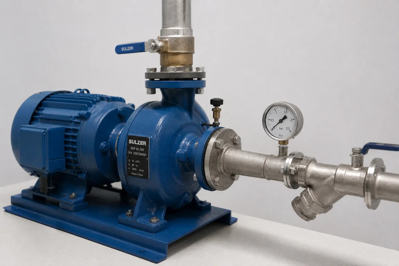
I’ve read more pump startup manuals than I care to admit. Most are monuments to over-engineered documentation: pages of compliance language, torque tables for bolts nobody is about to touch, and then—somewhere near the back—the actual priming instructions.
Here’s the friction point nobody talks about: centrifugal pump priming is not a plumbing ritual. It is a data-gathering exercise. Before the suction valve opens, before the casing vent cracks, before anyone calls for a start, someone needs to know what is in the suction line, where air can hide, how the seal is supported, and what “normal” looks like once the pump is running.
Skip that work and you are gambling with dry-run damage, cavitation, unstable flow, and seal trouble that will later be blamed on the pump.
This is the centrifugal pump priming data requirements checklist I wish someone had handed me on day one: five practical areas, concrete observations where they matter, and no fake certainty where the manufacturer’s IOM still has the final word.
Priming is a data problem disguised as a plumbing problem. If your checklist starts with “open the suction valve,” your checklist is already broken.
Confirming Suction Arrangement and Liquid Containment
The first question is not “what’s the pump model?” It is: can this pump retain or establish prime in this installation?
For most ordinary centrifugal pumps, the answer is no—not by themselves. If the impeller is not flooded at standstill and the unit is not specifically designed as self-priming, the system needs a liquid-retention arrangement, an external priming method, or a deliberate fill-and-vent routine before the motor is energized.
This is where a surprising number of startup problems begin. People see a suction pipe, see a pump, and assume the machine will somehow pull liquid into itself. It may not. A centrifugal pump moves liquid well; it is generally much less impressive when asked to move a suction line full of air.
Positive suction head versus suction lift
These geometries require different preparation. Confirm which one you have before touching a valve, because the distinction changes what “primed” means.
| Parameter | Positive suction head | Suction lift |
|---|---|---|
| Liquid source relative to pump | Above the pump centerline | Below the pump centerline |
| Initial liquid condition | Liquid should flow toward the pump by gravity | Casing and suction line may need external filling |
| Typical priming approach | Open the suction path and vent the casing until air is removed | Use a foot valve, vacuum priming device, ejector, or manual fill method as specified |
| Main startup risk | Air trapped in casing or at suction-line high points | Loss of prime, air leakage, incomplete suction-line filling |
| Key data to confirm | Static liquid level, valve position, vent result | Lift arrangement, priming method, foot-valve condition, ability to retain liquid |
A flooded suction arrangement is not an excuse to skip priming checks. It simply makes the job easier. Liquid may be available at the suction nozzle while air remains caught in the casing, seal chamber, an eccentric reducer, a vertical offset, or a dead-ended instrument branch.
With suction lift, the discipline needs to be tighter. Confirm whether the pump is self-priming, whether the suction line can retain liquid after shutdown, and whether the stated priming method actually matches the installed piping. A foot valve that leaks, a loose suction flange, or a vent left open can erase a careful priming job before the motor even turns.
Suction-side isolation and casing fill
Two conditions should be confirmed before any rotation check:
1. The suction-side isolation valve is fully open, unless the manufacturer’s startup sequence explicitly calls for another position. “Almost open” is not a valve position; it is an invitation to create an unnecessary restriction.
2. The pump casing and suction piping are filled with the pumped liquid as required by the pump design and suction arrangement.
For positive suction head, this may be as straightforward as opening the suction path and loosening the casing vent until a solid stream of liquid appears. For suction lift, filling may happen through a priming port, funnel connection, external vacuum system, or dedicated priming line. The important part is not the tool. The important part is proving that liquid has displaced air through the relevant volume.
A visual check helps, but do not stop at “the casing looks wet.” Record the source of liquid, the suction condition, the vent points used, and whether the line held liquid after filling. That small note can save hours later when a pump that “worked yesterday” suddenly will not take suction.
The quiet enemy: suction-side air leaks
A suction leak does not always leave a puddle. On the suction side, a poor gasket, loose threaded connection, worn packing, or compromised foot-valve seal can draw air inward without leaking liquid outward. The pump may start, run noisily, hunt for flow, and look mechanically guilty when the real issue is a small air path upstream.
Before startup, inspect the obvious suspects:
- Suction flange gaskets and bolting
- Threaded fittings and temporary commissioning connections
- Vent and drain plugs
- Instrument taps and gauge-root valves
- Foot-valve seating, if installed
- Suction strainer cover and gasket
- Any flexible connector or temporary hose used during filling
This is not busywork. The suction line is part of the pump’s operating environment. Treat it with the same suspicion you would give a mechanical seal flush line.
Venting Techniques and Trapped Air Elimination
A casing filled with liquid is not necessarily a system full of liquid. The suction line can hold air at every high point, and real installations are full of high points: a vertical offset to clear a foundation, an instrument tee, a check-valve body, a reducer installed the wrong way around, or a pipe run that looked level from the floor but is not.
Manufacturers are remarkably consistent on this point: vent until solid liquid appears, not until somebody decides it has probably been long enough.
The casing vent is operational, not decorative
The casing vent exists to remove air before startup. Use it deliberately.
Open the vent according to the pump’s procedure. Watch what comes out. Initial air discharge is expected; intermittent liquid and sputtering indicate that air remains in the casing or is still arriving from the suction line. A clean, continuous liquid stream is the useful observation. Then close the vent properly and inspect it for leakage.
The data worth writing down is simple:
- Which vent point was opened
- Whether air was discharged
- Whether liquid emerged as a solid stream
- Whether the casing had to be refilled
- Whether the system held its prime after the vent was closed
That record is more useful than a checkbox marked “primed.” A checkbox tells you nothing when the unit returns from maintenance and suddenly behaves differently.
Rotate the shaft by hand during venting
This is the step field crews skip because it feels ceremonial. It is not.
With the pump isolated, locked out as required, and safe to turn by hand, rotate the shaft several revolutions while the casing is being vented. This can help release air caught around impeller passages and in the seal-chamber area. It also gives you an early feel for abnormal rubbing, binding, or resistance before electrical power enters the conversation.
Do not force the shaft. If it does not turn smoothly, that is not a priming inconvenience to be solved with more enthusiasm. Stop and investigate coupling alignment, shipping restraints, internal contact, seal setting, or another mechanical issue.
High-point vents in the suction line
The casing vent cannot remove air trapped in a high point upstream of the pump. If the suction piping rises and falls before it reaches the casing, that elevated section needs to be considered during the startup plan.
A proper suction-line preparation review asks:
- Where is the actual highest point between the liquid source and pump?
- Is there a vent there, or another way to displace trapped air?
- Does the line slope continuously toward the pump where the design requires it?
- Are eccentric reducers oriented to avoid collecting air?
- Can a temporary vent be installed safely for commissioning if the permanent arrangement has none?
Do not accept noise, vibration, or weak early flow as normal commissioning behavior. Trapped air can reduce pump performance, make operation unstable, and create conditions that are hard on seals and internal components. The pump is often blamed because it is the loudest object in the room. The piping geometry is frequently the accomplice.
A filled casing is not automatically a primed pump. Air trapped upstream can reduce performance long before anyone notices where it came from.
Verifying Seal Flushing and Auxiliary Connections
Mechanical seals do not forgive dry running, inadequate cooling, or a flush path that exists only on the P&ID. If the pump has seal flushing, quench fluid, barrier fluid, cooling water, or any other auxiliary connection, that support system needs to be available before the motor sees power.
The error here is usually linguistic. Someone says the line is “open,” meaning the handwheel is turned. But a line can be open at one valve and still be blocked by a closed downstream valve, a plugged strainer, a stuck check valve, an empty reservoir, or an incorrect connection after maintenance.
Through-flow on every auxiliary connection
If there is a planned fluid path to or from the seal chamber, verify that fluid can actually move through it. The exact test depends on the seal plan and installation, but the principle does not change.
For each auxiliary connection, establish:
- The source of the flush, quench, cooling, or barrier fluid
- The upstream and downstream valve positions
- The condition of strainers, orifices, coolers, and small-bore tubing
- The expected direction of flow
- The available pressure indication, if gauges are fitted
- The destination of any return line
A pressure gauge is useful, but it is not a magic talisman. Static pressure alone does not prove circulation. Where the system design calls for flow, verify flow by the approved method for that arrangement: sight glass, flow indicator, temperature response, return condition, or the manufacturer’s prescribed commissioning check.
What “open” means here
Open means more than a valve handle aligned with the pipe.
It means the upstream supply is available, the route is not blocked, the return path is valid, and the system has been inspected for the small restrictions that cause disproportionate trouble. Seal support lines are often narrow. They are also easy to disturb during maintenance, insulation work, flushing, or temporary hose installation.
If a gauge reads zero when a supply should be present, do not invent a reason to continue. Trace the line. If the reservoir is empty, do not treat the level as an administrative detail. If an auxiliary cooler is isolated, do not assume the seal will “be fine for the test.”
Quench and barrier fluids
For double seals and systems using external barrier fluid, confirm the reservoir condition, fluid level, pressure status, circulation path, and alarm arrangement according to the seal plan. The required setpoints belong to the seal and pump documentation, not to a generic startup sheet.
The broader warning is straightforward: inadequate barrier-fluid support can reduce seal performance and damage seal faces. It may not announce itself immediately. A pump can appear to run acceptably during a short startup window while the support conditions are already wrong. That is exactly why this information belongs in the pre-start record rather than in someone’s memory.
Rotation Direction Safety Checks and Motor Jogging
This is where people get hurt and equipment gets damaged quickly. Rotation direction must be confirmed before the pump is allowed to operate as though everything is normal.
The arrow on the casing is not a logo
Every centrifugal pump has an intended rotation direction. It is usually marked on the casing, frame, guard, or documentation. Find it. Read it. Compare it with the motor’s observed direction.
For a three-phase motor, correcting rotation generally involves swapping two phases at the motor terminals or designated connection point, using the site’s electrical safety procedure. Do not improvise inside a live terminal box. De-energize, lock out, verify absence of voltage, make the correction through qualified personnel, and repeat the observation.
Momentary energize, not a start
A rotation check is a brief jog, not a startup attempt.
The motor is energized only long enough to observe shaft direction. The goal is not to build pressure, establish flow, or prove pump capacity. Those are separate activities that happen after the priming condition and valve sequence have been confirmed.
Before the jog, make sure guards, coupling conditions, personnel clearances, and process isolation match the approved procedure. If the pump can be checked uncoupled according to the manufacturer’s instructions, that may be the preferred approach. If it is checked coupled, the conditions need to prevent an accidental full operating run.
A casual “bump it and see” is not a method. It is what people call a method after nothing went wrong.
Repeat after every reconnection
Any motor disconnection, panel work, cable replacement, or rewiring event should trigger another rotation check. “Same motor, same pump” is not evidence that phase sequence survived maintenance unchanged.
This applies especially after:
- Motor replacement
- VFD installation or replacement
- Terminal-box work
- MCC or breaker maintenance
- Temporary generator operation
- Cable rerouting
- Any repair that required disconnecting leads
The check takes little time. Reversing the pump under actual operating conditions can create immediate hydraulic and mechanical trouble, and there is no prize for discovering it at full speed.
Recording Initial Operating Data and Baseline Metrics
The pump starts, flow comes up, everyone relaxes—and nobody writes down the numbers. Then later the seal begins to leak, bearing temperature rises, discharge pressure drifts, or the motor current changes. Without a startup baseline, every diagnosis begins with the same bad question: “Has it always done that?”
Initial operating data turns the first successful run into a reference point rather than a fading story.
What to log on day one
Once the pump reaches operating speed and stable conditions, record the available readings. Use the units shown on installed instruments and keep them consistent in the log.
- Suction gauge pressure
- Discharge gauge pressure
- Voltage on each phase
- Current on each phase
- Power draw where metering is installed
- Seal-flush supply and return conditions
- Bearing housing temperature
- Vibration reading where monitoring equipment is fitted
- Liquid temperature, particularly where vapor pressure or viscosity matters
- Valve positions and the final operating configuration
- Unusual noise, visible leakage, or unstable gauge behavior
The point is not to hit a mythical perfect number on day one. The point is to record the actual stable condition of this pump, in this system, with this liquid and this piping arrangement.
A suction pressure that looks ordinary in isolation may be meaningful when compared with the same pump months later. A current imbalance may be insignificant or may be the first clue of an electrical or mechanical issue. The baseline gives maintenance staff a place to start.
NPSH data gathering
Net positive suction head available, or NPSHA, needs to be considered against the pump’s required NPSH, NPSHR, before first startup—not after cavitation noise has already become part of the soundscape.
Gather the inputs that affect available suction head:
- Liquid level relative to pump centerline
- Suction pressure where applicable
- Liquid temperature
- Vapor-pressure sensitivity of the liquid
- Suction-pipe losses, including strainers and fittings
- Any temporary commissioning restrictions left in the line
- The manufacturer’s NPSHR information at the intended operating point
Some manufacturer guidance uses a stated margin between NPSHA and NPSHR as an initial screening criterion. Treat that as manufacturer-specific guidance, not as a universal number to paste into every installation. Hot liquids, volatile liquids, viscous services, changing tank levels, and unusual suction piping can all change the practical margin needed.
This is why net positive suction head data gathering is not a calculation to be buried in a commissioning binder. It is a live description of whether the pump has enough suction-side energy to operate without entering cavitation-prone conditions.
Build the comparison table now
Most plants have a historian, a CMMS, a commissioning record, or at least a logbook that is supposed to survive longer than the startup crew. Put the readings somewhere they can be found again.
A compact record can be enough:
| Reading | Initial stable value | Notes |
|---|---|---|
| Suction pressure | Recorded from installed gauge | Include tank level or suction arrangement |
| Discharge pressure | Recorded from installed gauge | Note discharge valve position |
| Motor current | Recorded for each phase | Note load condition |
| Seal support condition | Pressure, level, flow indication, or return status | Identify seal plan |
| Bearing temperature | Recorded after stabilization | Note ambient conditions if relevant |
| Vibration | Instrument reading or condition observation | State measurement location |
Tie the record to the equipment tag and the date of commissioning. Future troubleshooting becomes much faster when the question changes from “What should this pump be doing?” to “What changed from its known stable condition?”
If you did not write it down, you did not create a baseline. And without a baseline, every later repair begins as guesswork.
The Startup Sequence That Actually Matters
Commissioning procedures often bury the useful order under pages of administrative noise. The practical sequence is less glamorous and more reliable:
1. Confirm the pump type, suction geometry, liquid source, and approved priming method.
2. Inspect the suction path for open isolation valves, retained liquid, likely air leaks, and high points that require venting.
3. Fill the casing and suction arrangement as required; vent until liquid is solid at each relevant vent point.
4. Turn the shaft by hand where safe and permitted, looking for smooth movement and helping release trapped air.
5. Verify seal flushing, cooling, quench, barrier-fluid, and other auxiliary connections are genuinely available and correctly routed.
6. Confirm rotation direction by a controlled, momentary jog using the approved electrical and mechanical safety procedure.
7. Start the pump using the manufacturer’s valve-position and warm-up instructions for that model and service.
8. Once operation stabilizes, record the suction, discharge, electrical, seal-support, temperature, and vibration data available on site.
What not to do is just as important:
- Do not assume any centrifugal pump will prime itself.
- Do not treat a wet casing as proof that the entire suction system is free of air.
- Do not leave a seal support system to be checked “after it is running.”
- Do not energize the motor for a casual full-speed trial just to observe rotation.
- Do not run dry in the hope that the pump will establish prime on its own.
- Do not let the startup readings disappear into a conversation at the control panel.
The manufacturer IOM remains the final word on priming volume, allowable air content, external fill pressure, valve sequence, NPSH margin, seal-support settings, and model-specific restrictions. But the framework is broadly useful: establish liquid containment, eliminate trapped air, support the seal, verify rotation safely, and capture the baseline.
Do that work before first startup, and priming stops being a hopeful ritual. It becomes what it should be: a controlled handover from installation to operation.