Flange gasket materials: performance paths for industrial seals
It's 3:00 a.m. on a steam header, halfway through a production run, and a flange joint that was torqued down six months ago is quietly venting vapor past its seal.
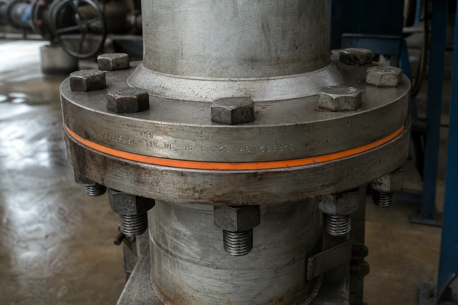
Flange gasket materials: performance paths for industrial seals
Compare car rental deals in United Kingdom
See available offersPartner link — DiscoverCars comparisonThe maintenance walk-down team catches it before the controller does — the tactile feedback of fingertips on the insulation, a faint hiss under the ambient roar of the plant — and within minutes the conversation turns to a single, deceptively simple question: which gasket material should go back in when this joint gets reassembled?
That question is where industrial flange gasket material selection really lives. In the real-world context of a working plant, it doesn't matter what color the sheet is, what trade name is printed on the box, or how similar the cut gasket looks next to the old one. What matters is whether the new material, the bolts, the flange faces, the torque procedure, and the process medium are going to behave like one coordinated system for the next year, the next five years, or the next twenty. A gasket isn't a part you buy; it's a system component whose material only earns its keep inside the bolted joint it lives in.
A gasket is not a part. It is a system component, and its material only matters inside the bolted joint it lives in.
The bolted-joint system: beyond material labels
When we walk a plant with operators, the most common reflex we see is someone reaching for "a 1/8" gasket sheet" without naming the service conditions first. We get it — when you have fifty flanges to think about in a shift, labels feel efficient. But industrial flange gasket material selection only works when you treat the joint as a small mechanical system with at least seven inputs that have to agree.
If the medium is hot caustic, then a general-purpose compressed fiber is going to swell and lose load retention faster than you'd like. If the pressure spikes during pump trips, then a gasket with low creep relaxation matters more than one with a glossy catalog compression number. If the flange face is pitted from a previous over-torque event, then a soft conformable sheet will squeeze into the pits and seal where a hard metallic ring would happily leak past the high spots. And if your maintenance team is already showing signs of operator fatigue from repeated re-torque rounds, the cost of "cheap" just doubled without anyone writing it down.
Here's the working checklist we use on the ground before any material gets pulled from the rack:
- Process medium: what exactly is on the other side of the flange — concentration, contaminants, water content, trace solvents.
- Operating temperature: steady-state, plus the worst-case upset the DCS will actually allow through.
- Operating pressure: steady-state, plus surge, water hammer, and pump-trip transients.
- Thermal cycling: how often this joint heats and cools, and by how much.
- Available bolt load: grade and size of stud or bolt actually in the joint, and how much preload it can realistically deliver with the lubrication condition on site.
- Flange condition: face finish, flatness, pits, warpage, and gasket location relative to the bolt circle.
- Applicable standards: ASME for geometry and pressure-temperature ratings, ASTM for material properties, and any plant-specific piping class spec.
If any of those is missing, then the "selection" is really a guess, and the joint will tell you so — usually by leaking on the worst possible shift.
Navigating ASME standards for gasket geometry and pressure
Once we've mapped the service inputs, the next question operators and engineers almost always ask is, "What standard should I be looking at?" On the ground, the answer is that there isn't one standard. There are at least four ASME documents that touch the same joint, and each one is doing a different job. Confusing them is how people end up buying a Class 300 gasket for a Class 600 service — or vice versa.
| Standard | Scope | What it actually tells you |
|---|---|---|
| ASME B16.5-2025 | Pipe flanges and flanged fittings NPS 1/2 through NPS 24; pressure-temperature ratings for Class 150, 300, 400, 600, 900, 1500, and 2500 (Class 2500 limited to NPS 12) | The pressure-temperature envelope your flange is rated for, and the bolting and joint-geometry context the gasket sits in |
| ASME B16.21-2021 | Nonmetallic flat gaskets: types, sizes, materials, dimensions, tolerances, markings | Whether your compressed fiber or PTFE sheet is dimensionally compatible with the flange it's being cut to fit |
| ASME B16.20-2023 | Metal ring-joint, spiral-wound, and metal-jacketed gaskets, plus filler material | The dimensional compatibility for metallic and semi-metallic families with ASME B16.5, ASME B16.47, and API 6A flanges |
| ASME PCC-1-2022 | Guidance for pressure-boundary bolted flange joints using ring-type gaskets inside the bolt circle | Assembly procedure, gasket technology, bolting methods, calculation methods, and troubleshooting for joints that won't seal |
A quick reality check we share on every audit walk: the ASME pressure class is the flange's rating, not the gasket's rating. We have seen operators insist that "we need a Class 600 gasket" when what they really mean is that the flange is Class 600 and the gasket has to be dimensionally and materially capable of surviving that pressure-temperature envelope alongside the available bolt load. A high-class flange with an under-spec gasket is still a leak waiting to happen. A low-class flange will not be rescued by a heroic material — it will simply yield the flange face.
If you are not sure which document governs your cut, the fastest honest answer is to ask which flange standard your piping class spec references. B16.21 nonmetallic gaskets are dimensionally tied to B16.5 and B16.47 flange geometry. B16.20 metallic gaskets are tied to the same flange families plus API 6A wellhead equipment. Mixing those references is one of the quieter ways joints end up misaligned.
Performance limits of PTFE, graphite, and compressed fiber
With the geometry question parked, the real industrial flange gasket material selection work happens in the four major material families. There is no universally "best" choice — only a better or worse fit for the service conditions you mapped in section one. Let's walk through how each family behaves in practice, with the limits our suppliers and our own field data have shown us.
Compressed fiber (non-asbestos sheet)
This is the workhorse on low-temperature, low-to-moderate pressure service. It is soft, conformable, easy to cut, forgiving of mildly pitted flange faces, and inexpensive. The trade-off is temperature ceiling and chemical envelope. In a heat-exchanger context, TEADIT describes general-purpose compressed fiber as broadly suitable up to around 400°F and at pressures consistent with ASME Class 300 flanges. Above that, the binders start to dry out and the sheet loses recovery. If you push compressed fiber into sustained steam service above roughly 450°F, you will likely be back inside the joint on the next turnaround.
PTFE and modified PTFE (including ePTFE and biaxially oriented grades)
PTFE is the chemist's friend. If you need broad chemical resistance, low extractables, food-grade cleanliness, or strong acid exposure, PTFE-family gaskets are usually the first conversation. The trade-offs are real, though. Standard PTFE creeps under sustained bolt load — the joint slowly loosens itself, and operators get used to re-torque schedules they shouldn't have to live with. Expanded PTFE (ePTFE) brings much higher compressibility — Lamons lists indicative compressibility figures of up to about 70% for ePTFE, compared to roughly 50% for flexible graphite, 25% for mica, and under 5% for solid metal — which makes it conformable on irregular faces but also adds bulk-creep concerns. Biaxially oriented PTFE narrows the creep gap considerably; one specific Lamons product (MATRIX CPG) carries a stated -450°F to 500°F (-268°C to 260°C) range and a maximum pressure around 1,235 psi. That is a specific construction, not a generic PTFE property. PTFE also has a temperature ceiling and oxidizer sensitivity you cannot negotiate with.
Flexible graphite
Graphite is the heat champion of the non-metallic world. Made from natural graphite with carbon content in the 90% to 99.9% range, flexible graphite has comparatively low creep — which means joints stay tight longer and re-torque intervals stretch out, taking a real bite out of operator fatigue. It also tolerates thermal cycling well because it does not harden with heat the way fiber does. The hard limit is oxidation. TEADIT is explicit: flexible graphite should not be used in oxidizing service above 840°F (450°C), because heated carbon reacts with oxygen and the resulting mass loss reduces bolt load. In a hot air, oxygen, or strong oxidizer service above that line, graphite will quietly shrink out from under the bolts. In steam or reducing service, the same material can run comfortably much higher.
Metallic and semi-metallic (spiral-wound, ring-joint, metal-jacketed)
When the temperature and pressure exceed what non-metallics can survive, we move into the metallic family. Spiral-wound gaskets combine a metal winding (often stainless or higher alloy) with a filler (frequently graphite or PTFE) and handle thermal cycling and high pressure very well. Ring-joint gaskets are solid metal rings for the most demanding service. Metal-jacketed gaskets sit between the two. ASME B16.20-2023 governs their dimensions and materials against B16.5, B16.47, and API 6A flanges. These constructions are not forgiving of bad flange faces — they need flatter, smoother seating surfaces than fiber or PTFE — and they cost more, but they buy you headroom in pressure and temperature that softer materials cannot match.
A compact side-by-side we use in plant walk-downs:
| Material family | Typical ceiling (service-dependent) | Compressibility (indicative) | Creep relaxation | Best-fit signal | Watch out for |
|---|---|---|---|---|---|
| Compressed fiber | ~400°F (TEADIT, heat-exchanger context) | Moderate | Moderate | Low-temp, low-to-mid pressure, mild chemicals | Binder dry-out, recovery loss at elevated temperature |
| PTFE / ePTFE / oriented PTFE | -450°F to ~500°F for oriented PTFE (specific product) | Up to ~70% (ePTFE) | Higher (standard PTFE) | Chemical resistance, purity, broad acid/base exposure | Sustained-load creep, temperature ceiling, oxidizer limits |
| Flexible graphite | Higher than non-metallics; avoid >840°F (450°C) in oxidizing (TEADIT) | ~50% | Low | High temp, thermal cycling, steam and hydrocarbon | Oxidation above 450°C in oxidizing media |
| Spiral-wound / ring-joint / metal-jacketed | Highest of the common families | <5% (solid metal) | Very low | High pressure, high temperature, ASME Class 600 and above | Flange face finish requirements, cost, less forgiving of damage |
Interpreting ASTM data: why compressibility isn't creep resistance
Here is where the day-to-day work gets subtle. The catalog cut sheet in front of you has a column for "compressibility" and a column for "recovery," and both come from a specific test — ASTM F36-15(2021). ASTM is clear about what that test is and is not. F36 measures short-time compressibility and recovery at room temperature on sheet, form-in-place, and certain cut gaskets. It is explicitly not a test for creep under prolonged loading, and it is explicitly not a test for recovery after prolonged loading.
That single distinction is the one we find ourselves explaining on almost every plant floor. A material can post a beautiful 15% compressibility and 50% recovery on an F36 datasheet and still lose half its seating stress over six months at elevated temperature. The ASTM test family that addresses that is different:
- ASTM F38-18(2024): creep relaxation of gaskets — the test that actually measures how much seating stress the material gives back over time.
- ASTM F2836-18(2024): gasket constants used in bolted-joint design — the
y,m,Gb,a,Gsinputs that go into PVRC-style joint calculations. - ASTM F104-11(2026): the classification system for sheet gasket materials — useful for describing a material, but ASTM itself limits how far you can lean on it for selection because it does not capture every property that drives sealing performance.
So when you are comparing two candidate sheets, the right comparison is not just compressibility. It is compressibility plus creep relaxation plus the gasket constants plus the manufacturer's elevated-temperature test data plus the chemistry of the medium. That is a heavier lift than a single-column catalog comparison, and it is exactly the lift that separates a guess from a selection.
Mitigating failure through assembly and environmental analysis
Even with the right material on the bench, the joint still has to be put together correctly. ASME PCC-1-2022 is the document we walk our crews through when we see repeated leaks in the same service, and it almost always points back to assembly. Bolt grade and size, lubrication condition on the threads and nuts, controlled tightening pattern, torque versus tension target, and the number of pass rounds all matter. A material that would have lasted ten years in a properly assembled joint can be destroyed in the first month by an uneven torque pattern that warps the flange face.
The environmental side of the analysis is just as real. Abrasive media will chew a soft conformable sheet at the ID over time. Thermal cycling loosens bolts even when the gasket itself is fine. Chemical aggressiveness that looks harmless at room temperature can attack a binder at process temperature. Pressure fluctuations that look small on a trend chart can produce enough load cycling to walk a poorly supported gasket out of position. And fire-safety status cannot be inferred from the presence of graphite, metal, or PTFE alone — the final gasket construction needs documented qualification to the required fire-test standard for the service.
If your selection process starts and ends with the material label, you are not selecting — you are hoping.
The honest end-state of industrial flange gasket material selection is that it is not really about picking a material at all. It is about understanding the bolted joint — the flange, the bolts, the procedure, the medium, the temperature, the pressure, the cycling — and choosing the material that lets that joint do its job without anyone on the floor having to think about it again for as long as possible. When we get that right, the maintenance tech on the 3 a.m. walk-down does not feel anything at the flange. That is the quiet victory the catalog numbers cannot quite capture, and it is the one that matters.