Bearing housing lubrication intervals: calculating precise grease replenishment schedules
At a speed factor above 500,000 min⁻¹·mm, a bearing housing is no longer a simple grease reservoir. It is a thermal and contamination-management system with a short response time.
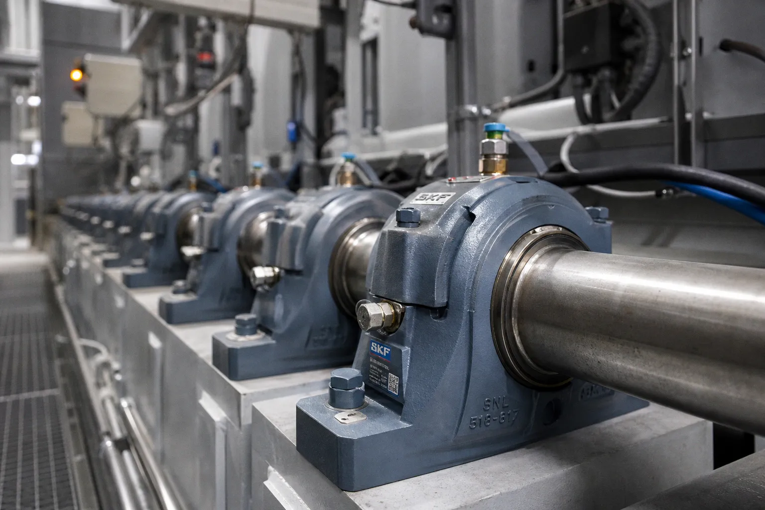
Apply a low-speed replenishment routine here and the result is predictable: grease churning, temperature rise, seal leakage, or accelerated lubricant breakdown.
A bearing housing lubrication intervals calculation guide must therefore produce two outputs, not one: the replenishment mass and the operating interval. These values are linked, but they are not interchangeable. A correctly sized grease shot delivered at the wrong interval still raises failure risk. A reasonable interval paired with an excessive grease shot does the same.
The recurring error rate in plant lubrication programs is treating the housing volume, NLGI grade, or a calendar period as the deciding variable. None is sufficient. Bearing geometry, rotational speed, load ratio, operating temperature, contamination exposure, sealing, purge paths, and grease chemistry all alter the result.
Start with replenishment mass, not a calendar date
For weekly, monthly, and yearly relubrication regimes, Schaeffler provides a practical starting formula:
m₁ = D × B × x
Where:
- m₁ is grease replenishment mass in grams.
- D is bearing outside diameter in millimetres.
- B is bearing width in millimetres.
- x is an interval factor.
The interval factor changes with the starting schedule:
| Starting interval | Factor x | Formula output |
|---|---|---|
| Weekly | 0.002 | Small, frequent replenishment mass |
| Monthly | 0.003 | Standard periodic replenishment mass |
| Yearly | 0.004 | Larger planned replenishment mass |
Take a bearing with an outside diameter of 120 mm and width of 30 mm. The monthly starting quantity is:
120 × 30 × 0.003 = 10.8 g
That figure is not a maintenance instruction. It is a starting quantity for a defined interval class. It does not prove that monthly relubrication is acceptable. It does not account for operating temperature, bearing load, contamination, or the ability of old grease to exit the housing.
This distinction reduces cognitive load in maintenance planning. First calculate the mass. Then establish whether the interval survives the application conditions. Combining those decisions into “one grease point every month” creates ambiguity and raises execution error rate.
A grease quantity is not a lubrication schedule. It is one parameter inside a lubrication schedule.
The formula is most useful where the bearing designation and dimensions are known, access is regular, and the housing has a defined purge route. It is less reliable as a standalone tool for sealed assemblies, heavily contaminated lines, high-speed machinery, or housings with no usable grease escape path.
Housing free space determines whether grease can do useful work
Grease does not disappear when a technician operates a grease gun. It either moves through the bearing, exits through a purge path, accumulates in the housing, or is pushed against seals. The housing determines which of these outcomes dominates.
Schaeffler guidance uses approximately 30% of free bearing space as a typical grease-fill reference. Timken guidance for typical industrial bearing cavities is approximately one-third to one-half full. These figures are not contradictory. They describe different application assumptions, cavity definitions, sealing arrangements, and operating conditions.
The incorrect interpretation is simple: fill every housing to a fixed percentage. That produces a high error rate because free space is not the same as total housing volume, and neither is equivalent to the space inside the bearing itself.
A practical assessment of bearing housing capacity has four parts:
1. Identify the actual free volume. Measure or obtain the cavity geometry after accounting for the bearing, shaft, seals, spacer rings, end covers, and grease fittings. Gross housing dimensions are not useful on their own.
2. Map the grease escape route. A housing with a grease valve, drain channel, purge port, or designed escape bore can accept a replenishment event differently from a sealed cavity. The first can evacuate aged grease. The second stores it.
3. Confirm whether the purge is functional under load. A nominal relief path blocked by hardened grease, paint, debris, or a poorly positioned plug has zero throughput. It cannot be counted as a purge mechanism.
4. Observe seal response. Grease appearing at a seal is not automatically proof of correct flushing. It may indicate excessive pressure, incompatible grease, or a housing with insufficient free space.
Where spent grease cannot be fully removed, the normal relubrication interval should be reduced to approximately 0.5 to 0.7 of grease operating life, tfq. This is a direct consequence of retained contamination and oxidized grease remaining in the system.
For example, an interval based on grease life alone may appear acceptable at 1,000 operating hours. If the housing cannot remove spent grease effectively, the practical planning range becomes roughly 500 to 700 hours before other application factors are applied. The interval is shorter not because the bearing suddenly consumes more grease, but because the housing cannot clear degraded material.
This is why calculating grease life in machinery without analyzing purge behavior produces false precision. Grease life is a lubricant property under operating conditions. Service interval is a system property.
Speed factor, load ratio, and temperature compress the schedule
The standard severity indicator for rotating bearing lubrication is the speed factor:
n × dₘ
Where:
- n is rotational speed in revolutions per minute.
- dₘ is mean bearing diameter in millimetres.
Mean diameter is generally derived from bearing geometry rather than guessed from shaft diameter. A maintenance record that lists only motor RPM cannot support a useful speed-factor assessment.
Schaeffler identifies very severe operating conditions when one or more of the following conditions applies:
| Operating parameter | Severe-duty threshold | Operational consequence |
|---|---|---|
| Speed factor | n × dₘ > 500,000 min⁻¹·mm | Very short intervals may be required |
| Load ratio | P/C > 0.3 | Grease film and bearing stress increase |
| Operating temperature | >140 °C | Lubricant thermal stability becomes the limiting factor |
| Combined exposure | Lower values acting together | Schedule may still need major reduction |
The combined-exposure clause is the part most often omitted. A machine does not need to exceed every threshold to become a lubrication problem. Moderate speed, elevated temperature, imperfect sealing, and water exposure can produce a worse result than one extreme parameter in an otherwise controlled environment.
At lower speed factors, larger replenishment quantities can be more tolerant. Schaeffler identifies n × dₘ no greater than 100,000 min⁻¹·mm as a condition where larger replenishment quantities are more suitable, particularly when the housing has large free space, a grease valve, or escape bores. The mechanism is straightforward: lower rotational speed reduces grease working and lowers the probability of a temperature increase caused by churning.
At high speed, the same grease shot is not neutral. Excess grease is worked repeatedly through the rolling contacts and housing. Mechanical energy becomes heat. The bearing temperature rises. The grease softens or oxidizes faster. The planned interval loses validity.
Replenishment during operation, at normal bearing temperature, is generally favorable because grease mobility and purge behavior are closer to actual conditions. This does not authorize indiscriminate greasing of unguarded machinery. It means the lubrication procedure should reflect how the assembly behaves in service rather than rely solely on a cold, stopped machine.
NLGI grade does not define the schedule
NLGI grade is frequently used as shorthand for grease suitability. It is not a valid shortcut.
NLGI consistency is determined by worked cone penetration under ASTM D217 or ISO 2137. NLGI Grade 2 corresponds to a worked penetration range of 265–295, measured in tenths of a millimetre. That describes consistency. It does not establish base-oil viscosity, thickener type, pumpability in a centralized system, water resistance, corrosion protection, load-carrying capability, or thermal life.
A Grade 2 lithium-complex grease and a Grade 2 polyurea grease can have entirely different compatibility and service behavior. Substituting one for the other because the number on the cartridge matches is a material-selection failure, not a lubrication adjustment.
For grease replenishment for industrial bearings, the minimum specification set should include:
- Base-oil viscosity at the operating temperature range, not only at catalog reference temperature.
- Thickener type and confirmed compatibility with the grease already in service.
- Bearing speed and the grease manufacturer’s speed capability.
- Temperature range and expected thermal stability at the real housing temperature.
- Water washout, corrosion protection, and contamination exposure.
- Pumpability through the actual line length, fitting geometry, and centralized lubrication distributor.
- EP or antiwear requirements where bearing load and sliding conditions justify them.
The interval calculation begins only after this material-selection layer is stable. A schedule cannot compensate for an unsuitable grease.
NLGI grade describes consistency. It does not describe grease life, compatibility, or bearing protection.
Manufacturer tables are starting regimes, not universal standards
Timken provides a suggested starting table for mounted tapered roller bearings operating eight hours per day. It is useful because it exposes how sharply conditions change the maintenance regime.
For clean and unexposed conditions, the suggested starting intervals are:
| Relative speed | Starting interval in clean conditions |
|---|---|
| Low speed: below 25% of maximum bearing RPM | 1 year |
| Medium speed: 25% to 75% of maximum RPM | 2 months |
| High speed: above 75% of maximum RPM | 2 weeks |
For moderate or exposed conditions, the starting interval contracts to one month at low speed and two weeks at medium speed. Under extreme or harsh conditions, low- and medium-speed applications may begin at one week. High-speed operation in moderate or harsh conditions requires application-specific treatment rather than a generic table value.
The throughput implication is clear. Exposure conditions can remove months from the schedule without any change in bearing size. Dust, washdown, process vapor, abrasive fines, intermittent flooding, and poor seal integrity do not merely contaminate grease. They increase the rate at which the grease system loses functional margin.
These intervals apply to a specific bearing context and duty assumption. They should not be copied across spherical roller bearings, deep-groove ball bearings, angular-contact arrangements, or assemblies with different housings and seals.
A sound bearing lubrication schedule uses manufacturer tables as boundary markers:
- A clean, low-speed assembly with stable temperature may support a long calendar interval.
- A medium-speed exposed assembly requires closer monitoring even when calculated replenishment mass is small.
- A high-speed assembly has low tolerance for excess grease and low tolerance for delayed replenishment.
- A severe-duty assembly should move from calendar-based servicing toward condition-informed lubrication control.
The table reduces planning latency. It does not eliminate engineering judgment.
Continuous feed is a different operating model
Some assemblies operate beyond the useful range of manual periodic greasing. Very short intervals, high temperature, high speed, or continuous contamination can make manual replenishment operationally inconsistent.
For extremely short relubrication intervals, Schaeffler gives a continuous-feed range:
m₂ = 0.5–20 × V [kg/h]
Where V is free space in the bearing.
For high-temperature greases with short thermal stability, a feed rate of approximately 1–2% of free bearing space per hour has proven appropriate in applicable cases. This is not a default setting for every automated lubricator. It is a regime for applications where thermal degradation and grease replacement rate dominate the maintenance model.
A continuous-feed system changes the control problem. Instead of asking whether a technician applied 10.8 g this month, the system must control:
- Feed-rate accuracy over the full temperature range.
- Lubricant line blockage and distributor performance.
- Pump pressure and the actual delivery quantity at each point.
- Purge behavior at the housing.
- Grease consumption rate against reservoir refill planning.
- Temperature trend after a feed-rate change.
An automatic lubricator with no verification loop can distribute failure faster than a manual grease gun. It reduces labor latency. It does not reduce the need for measurement.
The most useful validation signals are bearing temperature trend, grease appearance at controlled purge points, seal condition, vibration data where available, lubricant consumption, and inspection of removed grease for contamination or hardening. A single temperature reading is weak evidence. A stable temperature trend following a schedule change is stronger.
Build the schedule as a controlled system
Bearing housing lubrication intervals should be documented as an operating model, not a line in a preventive-maintenance calendar. The record needs the bearing designation, housing type, grease specification, calculated replenishment mass, trigger interval, speed factor, load condition, operating temperature band, purge arrangement, and observed results.
That record creates traceability. It also prevents a common maintenance failure: a schedule survives after the machine operating regime has changed. A conveyor speed increase, new washdown cycle, hotter process, different grease supplier, or modified seal can invalidate a schedule immediately.
The usable design heuristics are direct:
- Calculate replenishment mass from bearing geometry, then test the interval against speed, load, temperature, and contamination.
- Treat housing free space and purge throughput as schedule inputs, not mechanical details.
- Shorten intervals to roughly 0.5–0.7 of grease operating life when spent grease cannot be removed effectively.
- Do not fill housings to a universal percentage. Use the bearing, cavity, speed, and seal design.
- Escalate high-speed, high-temperature, and high-load assemblies beyond generic calendar schedules.
- Do not use NLGI grade as a grease-selection specification.
- Validate each schedule against temperature trend, purge behavior, grease condition, and operating history.
- Use continuous-feed systems only when their delivery rate and purge response can be measured.
The objective is not the longest interval and not the most grease. The objective is stable lubricant condition with controlled temperature, controlled contamination, and minimal seal stress. Everything else is administration.