Pump control cabinet integration: a roadmap to system startup
A pump control cabinet can pass a workshop inspection and still fail at the point where it meets the real installation.
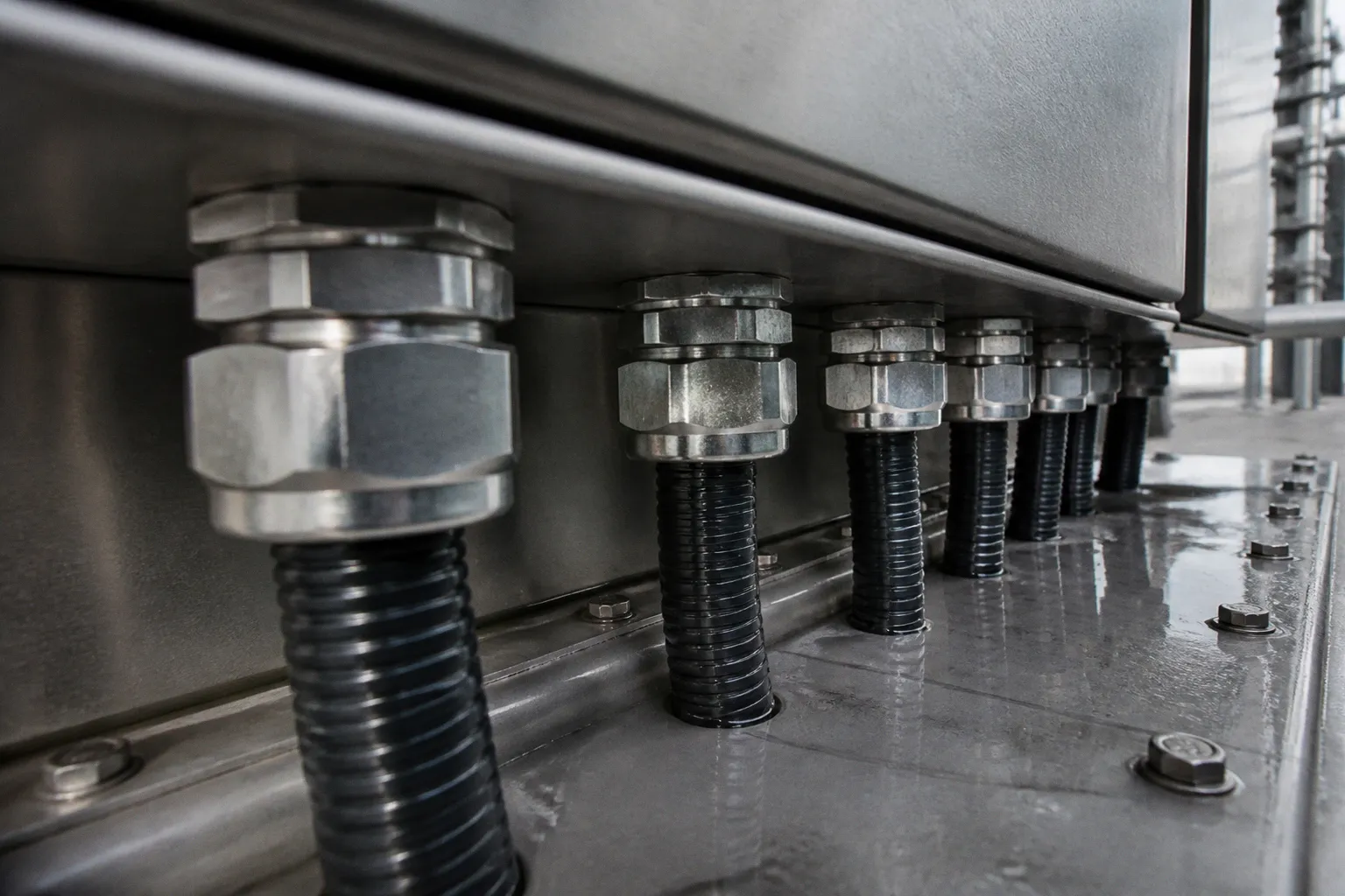
Pump Control Cabinet Integration: A Roadmap to System Startup
The reasons are usually familiar: insulation was never tested under the actual wiring conditions, the motor rotation was assumed rather than verified, or the control loop was tuned against a system that does not behave like the commissioning team expected.
The cost is not limited to replacing a component. A failed startup can hold up operators, electricians, process technicians, and production equipment at the same time. It can also expose weaknesses that are difficult to reproduce once the cabinet is back on the bench. That is why pump control cabinet integration steps should be treated as a sequence of evidence-based decisions rather than a final power-on ceremony.
The cabinet, motor, sensors, hydraulic equipment, and control software form one system. Each part has to be checked in the order in which its failure could affect the next one. Electrical integrity comes before energization. Rotation comes before loaded operation. Control tuning comes only after the pump and instrumentation are behaving correctly.
A successful startup is not the moment the motor turns. It is the moment the system turns, measures, protects, and responds as designed.
Standards and Environmental Hardening: Ensuring Compliance and Protection
Integration starts before any wire enters the enclosure. The cabinet must be suitable for the environmental and regulatory conditions of its installation site, and its construction must match the equipment it is intended to control.
For many industrial control panels in North America, UL 508A provides the principal framework for panel construction, component selection, and wiring practices. It is not the only standard that may apply. Fire pump controllers, for example, are subject to a different compliance path, including requirements associated with UL 218 and NFPA 20. A panel designed for a general water-transfer application should not be treated as interchangeable with a listed fire pump controller.
The first practical question is not whether the enclosure looks robust. It is what the enclosure will be exposed to:
- direct rain, snow, or ice;
- washdown water and windblown dust;
- condensation caused by temperature swings;
- salt air or corrosive wastewater atmospheres;
- chemical vapors, fertilizer, or treatment compounds;
- heat generated by drives, contactors, and power supplies inside the cabinet.
The NEMA classification should reflect that exposure, including the way cables, conduit, glands, and access doors are installed.
| Installation environment | Common enclosure direction | Protection concern |
|---|---|---|
| Covered outdoor location without direct water exposure | NEMA 3R or the specified equivalent | Rain, sleet, and ice formation |
| Exposed outdoor location or area near washdown | NEMA 4 | Windblown dust and hose-directed water |
| Coastal, chemical, or wastewater environment | NEMA 4X | Corrosion and corrosive liquid ingress |
| Indoor general-purpose electrical room | NEMA 12 where dust and dripping liquid are concerns | Dust and non-corrosive dripping liquid |
These are selection starting points, not substitutes for the enclosure manufacturer’s documentation or the site specification. A NEMA 4X box does not remain a NEMA 4X installation if a cable gland, drain, viewing window, or conduit fitting has a lower rating. The weakest penetration sets the practical limit.
Outdoor cabinet integration also requires attention to heat. A variable frequency drive produces heat even when the motor is operating normally. A sealed enclosure may protect against water while trapping that heat. If the internal temperature exceeds the rating of the drive, PLC, relays, or power supplies, the resulting fault may appear to be a software or wiring problem. In reality, the enclosure was undersized or its thermal management was never verified.
Grounding and bonding are equally fundamental. The protective ground must provide a continuous, low-impedance path from the equipment grounding conductor through the cabinet ground bus, enclosure, motor frame, and site grounding system. The door bonding jumper should be present where required, and removable backplates should not depend on paint-to-metal contact for continuity.
Before applying power, confirm the following in the as-built condition:
- Component compatibility. Breakers, contactors, overload devices, terminal blocks, disconnects, and protective components must be suitable for the panel design and the available fault current.
- Drawing-to-panel agreement. Wire numbers, terminal designations, conductor sizes, fuse ratings, and device labels should match the approved drawings. If the field wiring changed, the drawings must change with it.
- Ingress protection. Gaskets, conduit hubs, cable glands, and unused openings must support the enclosure rating.
- Heat and spacing. Drives, braking components, transformers, and power supplies need the clearances and ventilation specified by their manufacturers.
- Separation of circuits. Motor power, low-voltage control, analog signals, safety circuits, and communications wiring should be routed in a way that limits noise and preserves serviceability.
- Service access. A cabinet that technically works but cannot be safely isolated, tested, or repaired will create avoidable commissioning delays.
A neat panel is not automatically a safe panel. The useful test is whether another technician can identify the energy sources, trace a signal, isolate a motor, and restore the system without relying on memory.
Pre-Commissioning Electrical Integrity: Insulation Resistance and Megger Testing
Before the motor sees voltage, the power circuit should be tested as an electrical system: feeder, motor cable, terminations, motor windings, and any field junctions that belong to the circuit.
A megger, or insulation-resistance tester, applies a controlled DC test voltage and measures leakage through the insulation. The correct test voltage depends on the system voltage, motor design, cable construction, connected equipment, and manufacturer instructions. Values such as 500 V DC or 1,000 V DC may be appropriate in particular installations, but neither should be selected automatically.
The same qualification applies to the pass threshold. A reading of 1 MΩ is not a universal commissioning gate for every pump and motor. Some submersible-pump manufacturers use a value around that level as a minimum reference, while other equipment requires a higher reading or evaluates the result against a temperature-corrected baseline, previous test results, or a specified polarization trend. The OEM documentation and the applicable site procedure control.
The test sequence should be deliberate:
1. Isolate the equipment. Disconnect the motor from the VFD, soft starter, contactor, surge device, or other electronics that could be damaged by the test voltage. Open the relevant disconnects and verify the absence of voltage with a properly rated tester.
2. Identify stored energy. VFD output cables and long motor feeders can retain a charge. Follow the drive manufacturer’s discharge procedure, then ground the conductors for the required period before connecting the test instrument.
3. Confirm the test boundary. Record exactly what is included in the measurement. A test of the motor and drop cable is not equivalent to a test of the feeder and motor together.
4. Measure the required combinations. Depending on the equipment and procedure, this may include each phase to ground and phase to phase. Record every reading rather than writing down only the lowest or highest value.
5. Compare with the correct reference. Use the manufacturer’s minimum, the commissioning specification, and any available historical readings. Account for temperature and moisture conditions where the procedure requires it.
6. Discharge after testing. The conductors must be safely discharged and returned to the correct connection state before anyone handles them.
A useful record includes the test voltage, ambient and motor conditions, instrument identification, calibration status, connection point, and measured resistance.
| Measurement or comparison | How to interpret it |
|---|---|
| Phase-to-ground resistance | Compare with the pump and motor manufacturer’s requirement, not a generic value |
| Phase-to-phase resistance | Investigate imbalance or a low result before energization |
| Current reading versus previous reading | A significant decline may indicate moisture, contamination, or insulation damage |
| Cable-only versus motor-connected result | The difference can help locate the problem within the circuit |
| Stable result after drying and retest | More useful than a single isolated number, provided the value meets the specified requirement |
The most common procedural error is leaving the VFD connected to the motor leads. DC test voltage can reach the drive’s output components, DC bus, filters, or surge protection devices. Even when damage does not occur, those components can create parallel paths that make the reading meaningless. The motor circuit must be isolated in accordance with the equipment documentation.
Submersible installations deserve particular attention at the cable splice. A splice may look sound while allowing moisture to migrate into the insulation. If the result is marginal or materially different between conductors, do not convert that uncertainty into a pass simply because the motor has not yet tripped. Drying, inspecting, or remaking the splice may be necessary, followed by a documented retest.
A single acceptable measurement does not prove long-term reliability. Trend information matters. A motor that once measured well but now shows a substantial decline deserves investigation even if it remains above the site’s stated minimum. Conversely, a lower reading may be acceptable for one design and unacceptable for another. The decision belongs to the equipment specification and the qualified commissioning procedure.
Mechanical Verification: The Bump Test and Rotation Safety
Once the electrical circuit has been checked, the next question is simple but decisive: does the motor rotate in the correct direction, and can it do so without mechanical interference?
The bump test is a brief energization followed by immediate de-energization. Its duration should be kept to the minimum needed to observe rotation and should follow the pump manufacturer’s instructions. The test is not intended to run the pump under process conditions.
It can reveal several problems early:
- reverse rotation caused by phase sequence or termination errors;
- rubbing between an impeller and volute;
- coupling or bearing problems;
- debris in the hydraulic assembly;
- unexpected vibration or abnormal noise;
- incorrect motor connections or a missing phase.
The pump casing or motor documentation should provide the rotation reference. On many centrifugal pumps, reverse rotation reduces hydraulic performance and can impose mechanical stress on the impeller or shaft. On some pump types, the consequences and allowable test conditions differ, which is another reason not to treat every bump test as identical.
A controlled bump-test sequence
1. Verify that coupling guards, terminal covers, and other protective barriers are installed. A rotating coupling without its guard is an exposure, not a commissioning shortcut.
2. Confirm the pump’s required condition before starting. Some pumps must be primed; others must not be operated with liquid in the casing during a particular check. Follow the pump documentation rather than applying one rule to every design.
3. Check that the discharge and suction arrangement is in the correct safe state for the test. A closed valve, dry casing, or blocked suction can create a problem immediately after startup.
4. Energize the motor briefly and observe the shaft, coupling, or approved rotation indicator from a safe position.
5. De-energize and wait for the equipment to stop completely before making any correction.
6. If rotation is incorrect, correct the phase relationship using the approved termination method. With a VFD, do not move conductors on the drive output while energized; use the drive’s documented motor-phase or rotation procedure and isolate the equipment first.
7. Repeat the check and record the result.
A clamp meter or drive diagnostic screen may help identify a missing phase or obvious current abnormality, but a short bump does not establish that the motor is electrically balanced under load. Current imbalance limits should come from the motor, protection device, and commissioning specification. A generic percentage can be a useful investigative trigger in some procedures, but it is not a replacement for the manufacturer’s limits.
The bump test answers one narrow question: whether the pump can start in the right direction without an immediate mechanical warning. It does not certify loaded performance.
Full mechanical commissioning still requires operation at the intended duty point. Depending on the installation, that may include vibration measurements, bearing-temperature checks, coupling alignment verification, seal inspection, flow confirmation, and a review of suction conditions. A pump that sounds acceptable for a few seconds can still cavitate, overheat, or overload once the hydraulic circuit is fully open.
Advanced Control Logic: VFD Integration and PID Loop Optimization
A VFD changes pump commissioning from a simple starter check into a control-system exercise. The drive determines motor frequency, acceleration, limiting, protective behavior, and sometimes the PID response itself. The PLC may command the drive, receive status and fault information, and process pressure, flow, or level signals. If those interfaces disagree, the pump can hunt, oscillate, start too often, or remain at a frequency that the hydraulic system cannot tolerate.
Establish the VFD parameter baseline
Before tuning the loop, verify the parameters that define the motor and the operating envelope:
- Motor nameplate data. Enter rated voltage, current, frequency, speed, and power exactly as specified. An auto-tune procedure can improve the motor model, but it must be run under the conditions permitted by the drive manufacturer.
- Command and reference source. Confirm whether the drive receives a run command and speed reference from the PLC, hardwired terminals, a network, or its own internal control.
- Acceleration and deceleration. The correct ramp depends on motor inertia, pump type, hydraulic transients, and the need to avoid water hammer. A moderate starting value may be appropriate, but it must be validated during operation.
- Minimum and maximum frequency. The lower limit should protect the pump from unstable operation, inadequate cooling, or operation below the minimum recommended flow. The upper limit must respect the motor, pump, seals, bearings, and manufacturer’s overspeed restrictions.
- Overload and current protection. Settings must coordinate with the motor’s rated current, thermal capacity, overload relay, and upstream protection.
- Restart behavior. Define what happens after a power interruption, drive fault, low-level condition, or loss of feedback. Automatic restart may be acceptable in one process and unsafe in another.
- Fault handling. The PLC should distinguish between a commanded stop, a drive fault, a safety interlock, and a loss of communications. These conditions should not all produce the same operator message.
Industrial pump automation wiring deserves special attention around analog feedback. A pressure transmitter may use a current loop, a voltage signal, or a network connection. The PLC scaling must match the instrument range, and the signal should be checked at the transmitter, input terminals, and software display. A value that looks plausible on the HMI can still be incorrectly scaled.
Configure the PID loop around the actual process
The PID loop connects the measured process variable to the VFD output. Pressure, flow, and level systems do not respond in the same way. Pipe length, elevation, vessel volume, sensor location, valve position, pump curve, and demand changes all affect the response.
There are no universal P, I, and D values. Settings copied from another booster set may be unsuitable even when the pump motor and pressure transducer appear similar.
A practical tuning approach is:
1. Confirm that the sensor is correctly installed, scaled, damped, and located where it represents the controlled process rather than a local pressure spike.
2. Run the pump in a controlled manual or fixed-speed mode long enough to observe the process response.
3. Begin with conservative proportional action and little or no integral action. Increase proportional response gradually while watching for sustained oscillation.
4. Add integral action slowly to remove steady-state error. If the pump overshoots after a demand change or remains saturated at its frequency limit, check for integral windup and configure anti-windup behavior where available.
5. Use derivative action only when the process benefits from it and the signal quality supports it. Pressure transmitters with noise can turn derivative action into an amplifier for bad data.
6. Test several operating conditions: low demand, normal demand, rapid demand change, lead-pump handoff, and sensor-failure response.
| Control setting | If too conservative | If too aggressive | What to observe |
|---|---|---|---|
| Proportional response | Slow correction and visible error | Oscillation or unstable pressure | Time to approach setpoint |
| Integral action | Persistent offset | Overshoot and windup | Recovery after a demand change |
| Derivative action | Little effect | Noise and erratic output | Signal quality and damping |
| Minimum frequency | Poor response or insufficient flow | Unnecessary energy use or unstable pump operation | Pump curve and minimum-flow requirement |
| Ramp time | Slow pressure recovery | Current spikes or hydraulic shock | Motor current and pressure transient |
For a system with a pressure vessel, verify the vessel’s pre-charge using the procedure specified for that vessel and pressure-control arrangement. A commonly used reference may be around 1.5 bar in some standard water-booster systems, but it is not a universal target. The correct value depends on the pressure-switch settings, transducer range, vessel design, and system manufacturer’s instructions. The pump should be off, the relevant water pressure relieved, and the measurement taken with a suitable gauge.
Sensor setup is part of control tuning, not an afterthought. Confirm the transmitter’s supply voltage, polarity, loop current, engineering-unit conversion, alarm limits, and loss-of-signal behavior. A PID loop cannot compensate for a pressure sensor mounted in the wrong hydraulic location or a level probe affected by turbulence.
System Pressurization and Star-Delta Transition Management
The final integration work connects the cabinet’s logic to the hydraulic behavior of the system. This is where a panel can look correct electrically but still produce unstable pressure, nuisance trips, or damaging starts.
Pressurize the hydraulic circuit deliberately
Before applying a full automatic sequence, inspect the suction and discharge path. Confirm that isolation valves, check valves, strainers, bypasses, drains, and air-release arrangements are in their intended positions. Check that the pump is primed when required and that the system has a safe route for the initial flow.
Open valves gradually where the installation requires it. Sudden changes can produce water hammer, disturb a pressure transmitter, or create a transient that the VFD interprets as a process failure. During the first loaded run, monitor more than the HMI:
- motor current and drive output frequency;
- suction and discharge pressure;
- flow, if a flow instrument is available;
- vibration and bearing or motor temperature;
- seal leakage and unusual noise;
- pressure response at the sensor used by the control loop;
- start, stop, and fault timestamps.
The transducer location is the control point. A pressure gauge at the pump discharge may show a healthy value while the remote sensor sees a delayed or fluctuating pressure. Both readings can be correct because they describe different points in the system.
Rapid cycling is often blamed on the PLC before the hydraulic causes are examined. Incorrect vessel pre-charge, a leaking check valve, a pressure sensor with excessive damping, a badly located transmitter, or a narrow pressure deadband can all cause repeated starts. The cabinet logic should be reviewed together with the pipework and pressure equipment.
Manage star-delta transitions
For motors using a star-delta, or wye-delta, starter, the transition from reduced-voltage starting to full-voltage operation must be coordinated with the motor’s acceleration and the driven load.
The star connection reduces both starting voltage and starting torque compared with delta operation. This can be effective for appropriate pump loads, but it also means the motor may accelerate slowly when static head, inertia, or system pressure is high.
Two transition errors are common:
- Transition too early. The motor has not reached sufficient speed, so switching to delta creates a large current transient and may trip protection.
- Transition too late. The motor remains in the reduced-torque state longer than necessary, increasing heating and potentially leaving it unable to accelerate properly.
The correct transition time depends on the motor, pump, inertia, supply conditions, starter design, and hydraulic state. It should be established from the manufacturer’s documentation and observed current and speed behavior, not copied from a generic timer setting. Where the starter or protection relay supports it, capture the current profile during starting and review the transition event. A current spike alone does not identify the cause; it should be correlated with motor speed, pressure, and the starter’s contactor sequence.
| Starting method | Main characteristic | Typical consideration |
|---|---|---|
| Direct-on-line | High starting current and full starting torque | Suitable only where the motor and supply can tolerate the start |
| Star-delta | Reduced starting current and reduced starting torque | Requires a suitable load and correctly timed transition |
| Soft starter | Controlled voltage ramp | Useful where acceleration and hydraulic shock need to be managed |
| VFD | Frequency and voltage controlled throughout acceleration | Supports variable-speed operation and closed-loop control |
A VFD-driven motor does not use a conventional star-delta transition in the same way. The drive controls frequency and voltage continuously, but the motor’s terminal configuration must still match the drive and motor documentation. The absence of a star-delta timer does not remove the need to verify acceleration, current limits, minimum speed, and the pump’s hydraulic operating range.
From Startup to a Defensible Handover
Commissioning is complete only when the system’s behavior has been recorded, not merely observed once. A useful handover package should include the final schematics, panel photographs where appropriate, device and cable identification, insulation-test records, VFD parameters, PLC and HMI revisions, sensor calibration information, protection settings, alarm descriptions, and the results of loaded operation.
The final review should confirm that:
1. The enclosure, grounding, circuit separation, and environmental protection match the installation.
2. Motor and cable insulation were tested at the specified voltage and evaluated against the correct pump- and manufacturer-dependent criteria.
3. The motor starts in the correct direction and the pump reaches its intended duty without abnormal vibration, noise, heating, or leakage.
4. The VFD and PLC exchange the correct commands, references, statuses, and faults.
5. Pressure, flow, and level sensors are scaled and located correctly.
6. PID behavior is stable across the expected operating range rather than at one convenient test point.
7. Protective trips and interlocks have been tested without bypasses left in service.
8. Star-delta timing, soft-start behavior, or VFD acceleration has been verified against the actual motor and hydraulic load.
9. Automatic restart, lead-lag sequencing, low-level protection, dry-run protection, and loss-of-feedback behavior match the operating philosophy.
10. Operators have a clear record of what the system should do when a fault occurs.
The most valuable commissioning record is not a sheet filled with identical green ticks. It is a record that explains the conditions under which the values were obtained and gives the next technician a reliable baseline. Resistance readings, current trends, pressure response, and drive faults all become more useful when they can be compared with the original startup data.
Pump control panel installation is therefore only one part of integration. The real work is the controlled handoff between electrical construction, mechanical readiness, instrumentation, software, and operations. Treat those interfaces as separate systems and faults will hide between them. Test them as one coordinated installation, and the cabinet becomes what it should have been from the beginning: not just a box that starts a pump, but the protective and control center of a dependable water system.