VFD cable length limits for industrial pumps
The assumption that quietly shortens motor life is simple: a VFD and a pump motor are two boxes with a cable between them. Run the cable. Connect the ends. Start the pump.
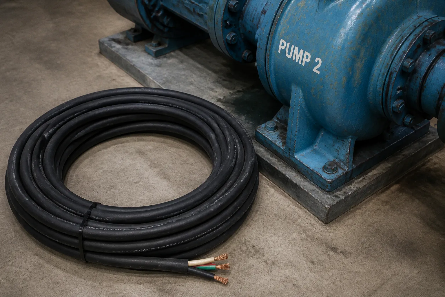
That cable is not a passive detail. On a long run, it becomes part of the electrical system. Its length, construction, grounding arrangement, impedance, and routing all affect what the motor actually sees at its terminals.
I have seen pump stations where a long shielded cable was installed between a drive and a submersible motor, while a reactor was added at the drive end as if that settled the problem. The installation looked complete. The motor still failed because the reactor had been asked to solve the wrong problem.
There is no single universal answer to the question of the vfd to motor maximum cable distance. A practical limit depends on the VFD, motor, cable, switching frequency, insulation system, protective devices, and the output equipment used to control the waveform. The distance printed in a manual is a starting point, not a substitute for checking the installation as a whole.
How the PWM waveform affects a cable and a motor
A VFD does not send a clean sine wave directly to the motor. It converts the incoming power to DC and then uses pulse-width modulation to synthesize an AC output. The output consists of fast voltage transitions arranged into a waveform that the motor’s inductance turns into usable current.
The transitions occur at the carrier or switching frequency, which is typically several kilohertz and may vary considerably by drive model and parameter setting. They are not limited to two events per fundamental cycle. The motor may run at a fundamental frequency of 50 or 60 Hz, but the VFD is switching many times during each of those cycles.
That distinction matters. The fundamental frequency determines the speed-related part of the waveform. The carrier frequency determines how often the VFD creates voltage edges, and those edges are what interact with the cable’s high-frequency behavior.
A short cable may not create a serious problem. A long cable is different. At high frequencies, the cable is no longer just a length of copper with negligible electrical characteristics. It has distributed capacitance, inductance, resistance, and a characteristic impedance. The motor has its own high-frequency impedance. When a fast edge travels from the VFD through the cable and reaches the motor, part of the wave can be reflected because the electrical properties of the cable and motor do not match.
The reflected energy returns along the cable and can combine with later voltage transitions. The result is a motor-terminal voltage that is higher and sharper than the nominal VFD output would suggest. The exact peak depends on the drive’s rise time, DC-bus voltage, cable length and type, motor impedance, termination conditions, and whether an output filter is installed.
The motor does not fail because it has seen one dramatic event. More often, the insulation system is subjected to repeated high dv/dt stress over a long operating period. The stress is concentrated at turns within the winding, especially when the motor was not designed for inverter service or when the cable and drive combination produces unfavorable peaks.
A motor’s insulation system has a finite tolerance for repeated high-dv/dt stress. A long PWM cable can turn a normal drive output into a long-term insulation problem at the motor terminals.
This is the reflected-wave phenomenon in pumps. It is particularly relevant when the motor is far from the drive, when the cable has low-loss insulation and sharp transmission characteristics, or when the motor’s insulation system has limited peak-voltage capability.
What else changes as the cable gets longer
Reflected voltage is only one part of the problem. A longer VFD-to-motor run also increases the cable’s capacitive load. High-frequency current flows through the distributed capacitance between conductors and from conductors to ground. That current can create several practical issues:
- Ground-fault or residual-current protection may nuisance-trip.
- The drive’s output stage may run hotter than expected.
- Cable shielding and grounding components may carry more high-frequency current.
- Common-mode current can contribute to bearing-current problems.
- Electromagnetic interference can become harder to control.
- Voltage drop can affect the motor, especially on heavily loaded or very long runs.
- The cable may require a larger conductor size or different construction than a basic ampacity calculation suggests.
The motor may continue running while these effects accumulate. That is why long-cable failures are often misdiagnosed. The pump starts, reaches speed, and appears healthy. Months later, the symptoms show up as ground-fault trips, bearing damage, winding faults, or unexplained drive alarms.
Why 30 meters is a baseline, not a universal limit
The frequently repeated 30-meter figure appears in many VFD installation guides because it is a useful reference point. At short distances, the interaction between the PWM output and the motor cable is usually easier to manage. As the run becomes longer, the chance of reflected-wave stress, leakage current, electromagnetic interference, and voltage drop increases.
But 30 meters is not a physical boundary at which every installation suddenly becomes unsafe. A 29-meter run can be poorly designed, and a much longer run can operate reliably when the drive, cable, motor, and filter are selected as a system.
The right question is not simply, “Is the cable longer than 30 meters?” It is:
- What does the VFD manufacturer permit for this drive and switching configuration?
- Is the motor rated for inverter duty?
- What peak voltage and dv/dt can the motor insulation withstand?
- What type of cable is installed?
- Is the cable shield terminated correctly at both ends?
- How much capacitive current does the run add?
- Is the drive fitted with an output reactor, dv/dt filter, or sine-wave filter?
- What does the applicable electrical code require for conductor sizing and protection?
- Is the distance measured along the actual route rather than as a straight-line drawing dimension?
Distance is a useful first filter. It is not the entire design.
The failure modes move with the installation
As the run stretches, different problems may become dominant:
1. Reflected voltage becomes more significant. The motor terminals can experience higher peak voltage and sharper transitions.
2. Capacitive current increases. The drive must charge and discharge the cable’s distributed capacitance on every switching transition.
3. Thermal behavior changes. High-frequency current, harmonics, installation method, and conductor construction can affect heating beyond what a simple line-frequency calculation shows.
4. Common-mode effects become harder to control. Poor shield termination or grounding can increase interference and bearing-current risk.
5. Voltage drop becomes more visible. The motor may receive less usable voltage under load, particularly when the conductors are undersized or the cable route is very long.
A long cable can therefore create problems even when the conductor’s basic ampacity appears adequate. Ampacity is necessary, but it is not the complete VFD cable calculation.
Practical distance bands for pump installations
Distance bands are useful for preliminary planning, provided they are treated as engineering prompts rather than guarantees. The following ranges are practical decision points, not universal limits for every manufacturer or motor.
| Approximate motor-lead length | Typical concern | Common design response |
|---|---|---|
| Up to about 30 m | Normal PWM installation concerns are usually easier to control | Use the cable type and grounding arrangement specified for the VFD and motor |
| About 30–90 m | Increased dv/dt, reflected-wave stress, and capacitive current | Check the drive manual; an output reactor or dv/dt filter may be appropriate |
| About 90–200 m | Filter selection becomes a central design decision | Compare a reactor, dv/dt filter, or sine-wave filter against motor and drive requirements |
| Beyond about 200 m | Long-run effects can dominate the installation | A sine-wave filter or a manufacturer-approved long-distance solution is often considered |
| Very long submersible runs | Multiple sections, junctions, wet-well routing, and high cable capacitance complicate the calculation | Use the complete route length and obtain written compatibility guidance from the drive and pump manufacturers |
Some VFD manufacturers publish separate cable-length limits for unfiltered operation, reactor operation, dv/dt-filter operation, and sine-wave-filter operation. Those limits may also change with carrier frequency, motor voltage, cable type, and the number of motors connected to one drive.
A small drive and a large drive do not necessarily have the same practical limit. The reason is not that one simple power threshold changes the laws of cable behavior. It is that drive output characteristics, protection settings, switching devices, cable capacitance, and the relative effect of leakage current can vary with the drive design.
The same length can therefore be acceptable in one installation and unsuitable in another. The number printed in a generic table should never override the specific drive manual.
Output reactors: useful, but not a universal cure
An output reactor is often the first mitigation device considered for a long motor cable. It is an inductor installed in series with the VFD output. Depending on its design and application, it can reduce the steepness of voltage transitions, limit current rise, reduce nuisance trips, and provide some protection against the electrical stress created by the cable.
For moderate cable lengths, that may be exactly what the installation needs. A reactor can be a sensible solution when the principal concern is edge rate, current ripple, or the need to moderate the interaction between the drive and the cable.
The limitation is that a reactor does not automatically turn a long PWM transmission line into a sine wave. It may reduce dv/dt without eliminating reflected-wave peaks at the motor. The result depends on the reactor’s impedance, the drive output, the cable, the motor, and the total length. It should not be selected merely because the cable is long.
A reactor also introduces voltage drop and heat. Its current rating must match the motor and drive application, and its installation must account for ventilation, enclosure temperature, and the manufacturer’s connection requirements.
The practical distinction is straightforward:
- Use a reactor when the application calls for moderated output transitions and the manufacturer allows that configuration.
- Do not assume that a reactor provides the same motor-terminal protection as a sine-wave filter.
- Do not use a reactor as permission to ignore the VFD’s maximum cable length.
- Recheck the motor voltage, current, acceleration behavior, and drive fault settings after installing it.
If the cable is moving into the range where reflected voltage and cable capacitance are the primary concerns, a reactor may be only one part of the solution.
A reactor shapes the edge. A sine-wave filter changes the waveform. They can occupy neighboring places in a design, but they are not interchangeable pieces of hardware.
When a dv/dt filter or sine-wave filter makes more sense
A dv/dt filter is more aggressive than a basic reactor. It is designed to control the rate of voltage rise and limit the peak voltage delivered to the motor. It can be appropriate when the motor insulation needs additional protection but a full sine-wave reconstruction is not necessary.
A sine-wave filter goes further. It uses an LC network to attenuate the carrier-frequency components of the VFD output so that the motor sees a waveform much closer to a sinusoidal voltage. It can significantly reduce:
- Motor-terminal peak voltage
- dv/dt stress on the winding insulation
- High-frequency capacitive current
- Electromagnetic interference
- Some common-mode and bearing-current problems
- The electrical burden created by very long motor cables
That does not make the filter free of consequences. A sine-wave filter adds voltage drop, heat, physical space, cost, and another set of installation requirements. The VFD may need a different parameter setup, and the filter must be selected for the motor’s voltage, current, frequency, and switching conditions.
The filter also needs to be installed in the correct location. In a conventional arrangement, the output filter sits between the VFD and the motor cable. The motor cable length still matters, and the cable between the filter and motor must remain within the filter manufacturer’s stated limits. A filter is not a license to extend the cable indefinitely.
A practical comparison
| Device | Main function | What it does not guarantee |
|---|---|---|
| Output reactor | Moderates current and voltage transitions; may reduce dv/dt and nuisance trips | It does not necessarily eliminate reflected-wave peaks |
| dv/dt filter | Limits voltage rise rate and peak stress more effectively than a basic reactor | It may not provide the same waveform quality as a sine-wave filter |
| Sine-wave filter | Reconstructs the output toward a sinusoidal waveform and reduces high-frequency content | It still requires correct sizing, cooling, parameterization, and cable-length checks |
The correct choice depends on the failure mode you are trying to prevent. If the issue is moderate dv/dt, a reactor may be sufficient. If the motor is sensitive to peak voltage or the cable is long enough for reflections to dominate, a dv/dt filter may be more appropriate. If the run is very long or the application requires a near-sinusoidal motor supply, a sine-wave filter is usually the more complete answer.
Submersible pumps: the distance is easy to underestimate
Submersible pumps make the submersible pump VFD cable run particularly unforgiving. The cable begins at the surface panel, travels through the well or wet well, passes through any junction or splice arrangement, and ends at the motor. The motor may be only a modest distance below the liquid level, but the actual route can be much longer once the panel location and tray or conduit path are included.
The total length is not just the well depth.
If the control panel is 30 meters from the well and the motor is 80 meters below the panel elevation, the electrical run is already approximately 110 meters before accounting for routing details, loops, vertical transitions, or the final connection into the pump assembly. A one-line diagram can make that distance look deceptively simple.
Submersible cable also has application-specific construction. It must tolerate immersion, mechanical handling, the pump’s starting and running conditions, and the electrical stress produced by the VFD. The cable supplied with a pump is not automatically suitable for every VFD arrangement. The pump manufacturer’s cable specification and the drive manufacturer’s cable requirements both matter.
Before approving the installation, confirm:
- The full route length from VFD terminals to motor terminals
- The cable’s inverter-duty suitability
- The insulation system’s peak-voltage capability
- The number and type of splices or junctions
- Shield and grounding continuity
- The cable’s ampacity in its actual installation environment
- The drive’s approved maximum cable length for the selected filter arrangement
- Whether the motor manufacturer permits operation from a PWM drive
- Whether the pump manufacturer requires a specific output filter or carrier-frequency limit
A submersible motor can be damaged even when the pump itself is correctly selected hydraulically. Hydraulic compatibility does not prove electrical compatibility between the motor, cable, and VFD.
Cable construction and installation details
The phrase “VFD-rated cable” is useful only if it describes the actual construction. A cable can be marketed as VFD cable while still requiring careful attention to shield coverage, conductor arrangement, grounding conductors, and installation method.
A suitable cable commonly includes symmetrical grounding conductors and a shield designed to control high-frequency current. The exact construction should follow the VFD manufacturer’s requirements. Some drives specify a particular shield coverage, a concentric copper braid, copper tape, or another low-impedance shield arrangement.
Shield termination is equally important. A long shield that is connected poorly at one end may fail to control common-mode current and electromagnetic interference. In many VFD installations, the shield is terminated with a low-impedance, high-frequency connection at both the drive and motor ends. The manufacturer’s instructions take precedence, particularly where the motor is submersible or the installation includes special bonding arrangements.
Routing matters as well:
- Keep motor cables separated from sensitive control and instrumentation wiring.
- Avoid unnecessary parallel runs with communication cables.
- Do not coil excess motor cable into a tight bundle near the drive.
- Maintain the manufacturer’s minimum bending radius.
- Use glands and terminations that preserve the shield and environmental rating.
- Bond metallic tray and enclosure sections continuously.
- Treat cable splices as part of the high-frequency circuit, not as invisible interruptions.
Cable size must also be selected for more than the motor’s running current. The calculation may need to consider voltage drop, installation temperature, grouping, short-circuit withstand, harmonic effects, and the VFD’s output characteristics. A larger conductor can reduce voltage drop, but simply increasing conductor size does not automatically solve reflected-wave or common-mode problems. Cable geometry and filtering may matter more than cross-sectional area for those issues.
The standards you cannot skip
VFD cable selection sits at the intersection of motor data, drive data, installation conditions, and electrical-code requirements. None of those elements replaces the others.
In the United States, NFPA 70, the National Electrical Code, addresses motor installations in Article 430, but the relevant requirements are distributed across different parts of that article. Article 430 Part II primarily addresses motor-circuit conductors, including their sizing and related installation requirements. Overload protection, motor branch-circuit short-circuit and ground-fault protection, motor disconnecting means, and related equipment are addressed in other portions of Article 430 and in associated code provisions.
That distinction matters because it prevents a common shortcut: treating “NEC 430” as one single rule that answers conductor size, overload settings, short-circuit protection, disconnecting means, and VFD installation all at once. It does not. The applicable sections must be identified based on the equipment and the installation.
The motor nameplate remains essential. It provides the motor’s rated voltage, current, frequency, power, service factor where applicable, and other information used for motor protection and application decisions. The VFD also has its own ratings, including input and output current limits, overload capability, short-circuit requirements, permissible motor combinations, and approved cable-length or filter configurations.
Proper conductor and protection sizing must account for both sets of information, along with the applicable code and the manufacturer’s instructions. It is not a universal rule that the VFD output replaces the motor nameplate as the sizing basis. Nor is it safe to size everything solely from the motor nameplate without checking the drive’s ratings and installation requirements.
IEC-based installations require the same discipline, although the structure and terminology differ. IEC 60364-5-52 addresses the selection and erection of wiring systems, including current-carrying capacity and voltage-drop considerations. Additional standards and manufacturer documentation may apply to the drive, motor, machinery, functional safety, EMC, and protective coordination.
For a long run, separate the questions instead of forcing them into one calculation:
1. What conductor size is required? Consider motor data, drive limitations, installation method, ambient conditions, grouping, and voltage drop.
2. What overload protection is required? Follow the motor, drive, and applicable code requirements.
3. What short-circuit and ground-fault protection is required? Use the equipment ratings and the applicable protective-device rules.
4. What disconnecting means are required? Check the location, accessibility, rating, and code provisions.
5. What cable and filter arrangement is permitted? Follow the VFD and motor manufacturers’ long-cable guidance.
6. What EMC and grounding arrangement is required? Follow the drive documentation and the site’s bonding practice.
The goal is not to choose the largest cable and assume the rest will take care of itself. The goal is to satisfy conductor, protection, motor, drive, filter, and installation requirements at the same time.
Putting the design together
When sizing a VFD-to-pump cable run, I work through the installation in a fixed order because skipping the early measurements usually creates expensive confusion later.
1. Measure the actual route
Measure from the VFD output terminals to the motor terminals. Include the vertical drop, tray route, conduit route, junction-box loops, and any section between a filter and the motor. Do not rely on the distance between equipment symbols on a drawing.
For a submersible pump, include the entire descent and every above-ground section. If the pump can be raised or lowered during maintenance, check whether the operating arrangement changes the cable length or creates a different routing condition.
2. Identify the complete drive and motor combination
Record the VFD model, voltage class, output current, carrier-frequency range, overload rating, and approved filtering options. Record the motor’s rated voltage, full-load current, frequency, insulation system, and inverter-duty status.
The drive and motor should be evaluated together. A drive that can operate a motor electrically is not necessarily approved for every cable length or filter arrangement.
3. Confirm the cable construction
Check the conductor size, insulation, shield, grounding conductors, temperature rating, wet-location suitability, and installation method. For submersible applications, confirm that the cable is suitable for the depth, liquid, mechanical conditions, and pump connection method.
Do not assume that a shielded cable is automatically the right cable. Shield type and termination quality affect high-frequency behavior.
4. Select mitigation based on the actual concern
Use the distance as an initial guide:
- Short runs: Follow the VFD’s standard cable and grounding instructions. An output filter may not be needed, but the motor must still be suitable for the drive.
- Moderate runs: Check whether an output reactor or dv/dt filter is required. Consider capacitive current and the motor’s insulation capability, not just the cable length.
- Long runs: Compare the manufacturer’s limits for reactor, dv/dt-filter, and sine-wave-filter configurations. A reactor alone may not control the motor-terminal peaks sufficiently.
- Very long runs: Treat the filter as part of the original system design. Confirm voltage drop, filter losses, cooling, parameter settings, and the allowable cable length downstream of the filter.
5. Recheck protection and conductor sizing
After selecting a filter or changing the cable, revisit the conductor and protection calculations. The VFD’s input-side protection is not automatically the same as the motor’s overload protection. The motor’s nameplate data, the drive’s ratings, and the code requirements must remain aligned.
A filter can change voltage, current, waveform, heat, and fault behavior. It should not be added to an existing panel without checking the consequences.
6. Configure and commission the drive
Long motor cables often require more than hardware. Carrier frequency, motor data, acceleration and deceleration ramps, current limits, thermal modeling, ground-fault sensitivity, and skip-frequency settings may all affect operation.
Use the manufacturer’s parameter recommendations rather than leaving every value at its default. Verify the motor current, terminal voltage where appropriate, fault history, filter temperature, and grounding behavior under representative load conditions.
The distance limit is a system limit
The most misleading VFD advice is the kind that offers one number with no conditions attached. A statement such as “maximum cable length: 100 meters” is incomplete unless it also tells you whether the number applies to a particular motor, carrier frequency, cable type, filter, voltage class, and installation arrangement.
The practical limit is created by the weakest part of the system:
- A non-inverter-duty motor can become the limiting component.
- A high carrier frequency can increase switching-related stress.
- A cable with high capacitance can increase leakage current.
- Poor shield termination can turn an acceptable cable into an EMC problem.
- An undersized conductor can create voltage drop and thermal issues.
- A reactor selected without checking motor-terminal voltage may provide false confidence.
- A filter installed without considering its downstream cable length may solve one problem and create another.
This is why the correct answer to vfd cable length limits is always conditional. The distance must be matched to the drive and motor documentation, not copied from a generic rule of thumb.
The verdict
Thirty meters is a useful starting line, not a universal ceiling. Beyond it, the installation deserves a closer look. Around the moderate-length bands, a reactor or dv/dt filter may be appropriate. As the run becomes longer and reflected-wave or capacitive-current problems dominate, a sine-wave filter may be the more complete solution.
For pump installations, especially submersible ones, measure the complete route before selecting the hardware. The well depth is only part of the distance. The motor cable, drive, filter, grounding system, protection, and code calculations all belong to the same design.
The standards matter, but so does reading them accurately. Motor-circuit conductors, overload protection, short-circuit and ground-fault protection, and disconnecting means are related requirements, not one interchangeable paragraph. Motor nameplate data and VFD ratings are both part of the design basis.
Stop treating the cable between the VFD and the pump as plumbing. It is an active electrical component in the system. Choose its length, construction, protection, and filtering as deliberately as you choose the pump and the drive. The motor that is still running after years of service is the evidence that the cable design was doing its job.