Pump preventive maintenance schedules: avoiding hidden downtime traps
A pump can lose 10% or more of its wire-to-water efficiency from wear-ring and rotor erosion before it produces a failure alarm that forces action. The unit still starts. It still delivers flow. It still appears available in the CMMS.
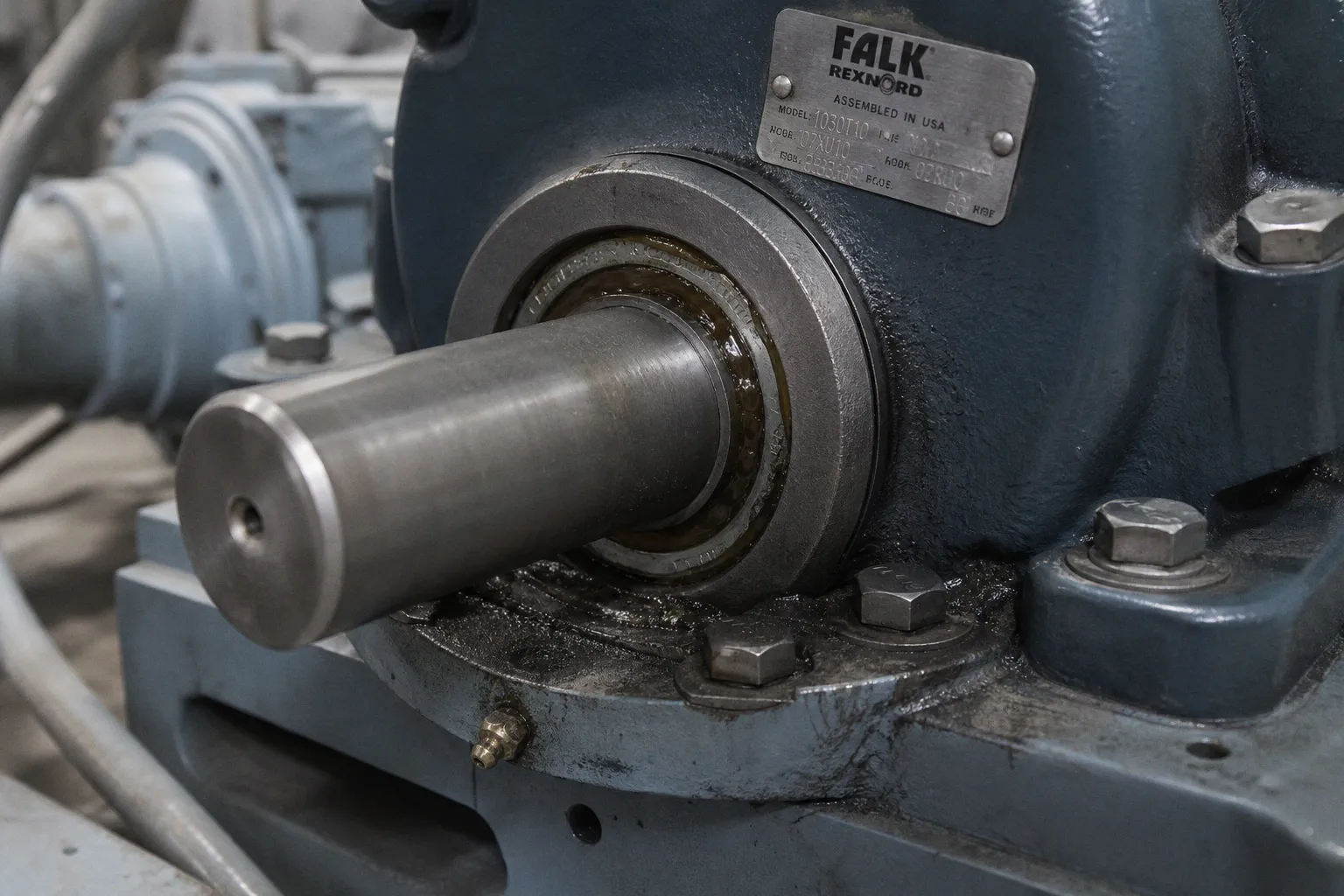
It is already consuming more power, shifting its operating point, and reducing process margin.
This is where pump preventive maintenance scheduling traps begin. Most are not caused by a missing task. They are caused by a bad decision model: the same interval for every asset, a leakage observation classified without context, a vibration number copied from another machine class, or a work order that treats energy isolation as paperwork after the repair plan is written.
The maintenance schedule is an operating interface. Its throughput is measured in completed work that prevents loss. Its latency is measured from early degradation to corrective action. Its error rate is measured in unnecessary interventions, missed degradation, and avoidable shutdowns. A calendar alone cannot control those variables.
The fixed calendar creates a false sense of coverage
A recurring work order is easy to administer. “Inspect every 30 days” fits a scheduling system. It does not necessarily fit a pump.
Two nominally identical pumps can have completely different degradation rates. One handles clean, cool water near its preferred operating range. The other runs intermittently, sees suspended solids, experiences frequent starts, and operates with piping loads that shift after every thermal cycle. Applying the same interval to both creates two failure modes:
- The stable pump receives low-value intervention. Labor throughput is consumed without reducing meaningful risk.
- The stressed pump degrades between inspections. The schedule reports compliance while the equipment moves toward failure.
- Technicians learn that recurring tasks rarely find anything. Inspection quality declines because the cognitive load of sorting signal from routine noise is too high.
- The maintenance planner mistakes task completion for condition control.
The correct model combines preventive actions, predictive actions, and periodic efficiency testing. These are separate information channels. A lubrication route does not replace vibration trend data. A monthly visual inspection does not reveal hydraulic erosion. A vibration route cannot determine whether a packing gland has been overtightened.
The interval should therefore emerge from asset context, not from a generic PM library.
| Scheduling input | Low-consequence utility pump with installed standby | Process-critical pump with no practical backup |
|---|---|---|
| Failure consequence | Local repair and limited production effect | Production stop, safety exposure, or process upset |
| Preferred monitoring model | Basic preventive tasks and operator observation | Condition-based monitoring plus planned corrective windows |
| Vibration program | May be selective if replacement is simple | Trend data normally has high value |
| Efficiency testing | Periodic or triggered by performance concern | Regular baseline and trend comparison |
| Spare strategy | Unit replacement may be faster than repair | Critical spares, seal kits, bearings, and repair scope preplanned |
| Inspection interval | Based on duty, environment, and history | Based on duty, degradation trend, and remaining operating margin |
This is not an argument against calendar work. Calendar work is still required for repeatable basics: verifying lubrication condition, inspecting guards, confirming leakage behavior, checking fasteners where relevant, and reviewing operating observations. The error is treating the calendar as the diagnostic system.
A completed PM is an activity record. It is not evidence that the pump remains healthy.
Build schedules from failure consequence first
Pump service schedule optimization starts with segmentation. Do not begin with “daily, weekly, monthly, annual.” Begin with operational loss.
A useful asset segmentation has four inputs:
1. Process criticality. Determine what stops if the pump stops. Include quality losses, environmental exposure, production constraints, and restart time. A pump with installed redundancy is not automatically noncritical if the standby unit shares the same suction problem or has not been tested under load.
2. Degradation velocity. Review how quickly known failure modes progress. Abrasive service, unstable suction conditions, dry-running exposure, thermal cycling, frequent starts, and contaminated lubrication reduce the safe interval between observations.
3. Detectability. Some failure modes announce themselves early. Bearing degradation can often be tracked through temperature, audible noise, vibration, and oil condition. Internal wear may require efficiency testing or hydraulic performance comparison. A schedule must provide the correct sensor for the failure mode.
4. Intervention cost. A complex seal replacement may introduce alignment drift, assembly error, and startup risk. If an intervention has high execution risk, doing it early without evidence is not conservative. It is simply another source of error.
The resulting intervals are site-specific. No authoritative universal daily, monthly, quarterly, or annual schedule exists for all industrial pumps. Pump design, fluid, operating duty, lubrication method, installation quality, and consequence of failure change the interval.
A schedule should state the trigger as clearly as the date. “Inspect pump monthly” is vague. “Inspect bearing housing temperature trend during normal duty; investigate sustained deviation from the established unit baseline” is operational. It tells the technician what to observe and tells the planner what produces follow-up work.
Leakage is not one condition
Leakage is frequently handled with the lowest-quality decision rule in pump maintenance planning: liquid visible equals seal failure.
That rule is wrong for packed pumps. Packing needs controlled leakage to lubricate and cool the packing interface. U.S. Department of Energy guidance cites a usual range of 2 to 60 drops per minute for packing, with the actual allowable rate governed by the pump and packing manufacturer’s instructions. The range is not a universal acceptance criterion. It is evidence that zero leakage is not the target state.
Overtightening packing to eliminate visible leakage can create the very damage the schedule is intended to prevent. Shaft or sleeve wear increases. Friction rises. Motor power use can rise. The gland adjustment becomes a forced maintenance event instead of a controlled operating condition.
Mechanical seals require a different branch in the decision logic. Their allowable leakage is manufacturer-specific. Leakage beyond that specification requires action. The schedule cannot use the packing rule for a mechanical seal, and it cannot use a generic mechanical-seal number without the seal documentation.
The maintenance route should force this distinction before the observation is logged.
| Observation | Packed pump interpretation | Mechanical seal interpretation | Required next action |
|---|---|---|---|
| Controlled, stable leakage | May be normal and necessary for cooling and lubrication | May indicate seal condition issue depending on specification | Identify seal type before generating a corrective work order |
| Leakage increases over several observations | Check packing adjustment, sleeve condition, fluid conditions, and gland temperature | Compare against manufacturer limit; inspect for seal-face or support-system issue | Trend rate and operating context, not only presence of liquid |
| No packing leakage after adjustment | Potential overtightening risk | Not applicable as a general indicator | Check temperature, shaft/sleeve condition, and power impact |
| Leakage with vibration or abnormal bearing temperature | May indicate a broader alignment or shaft-motion problem | May indicate secondary damage, not only seal failure | Escalate to coupled fault analysis |
The interface design matters here. A technician should not see a binary field marked “leak: yes/no.” That creates a binary dataset from a non-binary condition. Record seal type, approximate leakage behavior, trend direction, operating temperature where relevant, and whether the unit is running at normal duty.
This reduces cognitive load at the point of diagnosis. It also reduces the error rate of automatically generated work orders.
Efficiency loss is maintenance data, not an energy footnote
A pump can remain mechanically intact while becoming hydraulically inefficient. Wear-ring clearance growth and rotor erosion are common examples. The pump may keep meeting a reduced process demand, hiding the loss in excess operating hours, throttling, or higher speed. The utility meter records the penalty. The PM schedule does not.
Wire-to-water efficiency is the relevant performance relationship: electrical input compared with hydraulic output delivered by the pump. A deterioration of 10% or more can occur from wear-ring and rotor erosion before complete failure. That is a maintenance signal.
The problem is not that teams lack efficiency data. Most facilities have some combination of motor power, discharge pressure, suction pressure, flow, speed, and runtime. The problem is that the data is rarely assembled into a stable comparison.
A practical efficiency-trending process has four stages:
1. Establish a baseline under defined operating conditions. Record flow, suction and discharge conditions, power input, speed, fluid characteristics where they materially affect performance, and valve position or process state. A baseline taken during recirculation or unstable process demand has low diagnostic value.
2. Repeat measurements at comparable duty. The objective is not laboratory-grade pump testing every week. The objective is a reliable directional trend. Comparing unrelated operating points produces false alarms.
3. Separate pump degradation from system change. A rising power draw at the same flow may indicate internal loss, but it can also reflect fluid changes, increased static head, fouling elsewhere in the system, or a control change. Pump maintenance planning errors often begin when a single measurement is assigned to the nearest component.
4. Trigger inspection before operational failure. A confirmed adverse trend should generate a scoped investigation: impeller condition, wear-ring clearances, internal recirculation evidence, suction condition, alignment, and operating-point review. It should not automatically generate a full overhaul.
The work order needs a performance context. “Pump inefficient” is not a failure mode. “Measured hydraulic output declining against prior baseline at equivalent speed and process condition” is a diagnostic statement.
If efficiency is not trended, internal hydraulic wear becomes visible only after it has already consumed energy and process capacity.
This is also where maintenance and operations need one shared record. Operations sees rising runtime or a valve that must be opened further. Maintenance sees a pump that has not failed. Neither view is sufficient alone. The combined trend has lower latency.
Alignment drift is a system condition
Alignment is often treated as a commissioning task and then forgotten until coupling wear, bearing damage, seal distress, or high vibration produces a repair event.
That sequence is inefficient. Pump and motor alignment changes over time. Foundation feet can move. Piping loads can change. Thermal growth can expose an installation that was aligned cold but not in operating condition. A seal replacement can alter assembly geometry. A motor swap can introduce soft foot or coupling setup error.
Dial-indicator total indicated runout, also called full indicator movement, is a common alignment measurement. Laser tools can improve repeatability and data capture, but the tool does not solve the process problem. The schedule must specify when alignment is checked and what event triggers remeasurement.
Alignment should be included after events that change the mechanical system:
- Pump or motor replacement.
- Seal, bearing, coupling, or sleeve work that requires disassembly.
- Piping modification or support adjustment.
- Foundation repair, grout work, or movement evidence.
- Repeated seal or coupling failures without a confirmed primary cause.
- Significant thermal-service changes.
- An adverse vibration trend that persists after simpler causes are excluded.
The trap is separating maintenance activities into isolated tasks. Seal technicians adjust the seal. Millwrights align the train. Reliability engineers review vibration data. Each group can close its work order while the coupled system remains unstable.
A good schedule connects the tasks. It includes a post-maintenance verification sequence: alignment confirmation where the work scope warrants it, guard restoration, startup observation, leakage behavior, bearing temperature stabilization, vibration baseline update, and performance check at normal duty. This is not extra administration. It is the control loop that prevents maintenance-induced defects from becoming the next shutdown.
Vibration numbers without machine context increase error rate
Vibration monitoring has high value when it is used as a trend. It has low value when it is used as a generic pass/fail sticker.
ISO 10816-7:2009 provides vibration-evaluation guidance for industrial rotodynamic pumps above 1 kW when measurements are taken on non-rotating parts such as bearing housings. But it is not a universal alarm table that can be pasted into every CMMS. The applicable evaluation depends on pump type, support condition, measurement location, operating speed, machine class, and the site’s own acceptance criteria. ISO lists the standard as published and to be revised, while ISO/AWI 20816-7 remains an approved work item.
That status matters because teams often search for one threshold, find one, and build a route around it. The result is false precision.
A usable vibration program needs an explicit measurement architecture:
- Measurement point definition. Mark the bearing housing locations and measurement directions. A reading from one location cannot be directly compared with a reading taken elsewhere.
- Operating-state definition. Capture data at comparable load, speed, and process condition. Variable-speed pumps require operating-point labels.
- Baseline ownership. Establish a known-good reference after proper installation or verified repair. Without a baseline, the first reading is only a number.
- Trend rules. Investigate meaningful change from the asset baseline. Do not wait for a universal red limit that may not apply to the machine.
- Escalation path. Define whether a deviation leads to repeat measurement, lubrication review, alignment check, process review, oil analysis, or planned shutdown inspection.
Vibration-based predictive maintenance is not economically justified for every pump. The value depends on criticality. If catastrophic failure stops operations, trend monitoring can reduce downtime latency. If a small pump has reliable standby capacity and is quickly replaceable, intensive monitoring may consume more resources than it saves.
The schedule should reflect this decision rather than treating every asset as a rotating-equipment laboratory.
Service execution fails when energy control is bolted on at the end
The most dangerous preventive maintenance pitfall is procedural separation. The planner scopes the mechanical task. The supervisor later adds lockout requirements. The technician discovers stored energy, blocked-in pressure, hot fluid, or an uncontrolled process connection at the job site.
That is not a field problem. It is a planning failure.
For applicable U.S. general-industry work, OSHA 29 CFR 1910.147 establishes minimum requirements for hazardous-energy control when unexpected energization, startup, or release of stored energy could cause injury. The core sequence includes isolating energy sources, dissipating or restraining residual energy, and verifying isolation before service begins.
For pumps, hazardous energy can include more than motor electrical supply:
- Electrical energy at the motor starter, local disconnect, variable-frequency drive, or automatic control circuit.
- Hydraulic pressure in the casing, discharge line, seal flush arrangement, or accumulator.
- Pneumatic energy in actuators or control devices.
- Gravity or mechanical energy in elevated equipment, couplings, and rotating assemblies.
- Thermal energy from hot process fluid, steam tracing, or heated casing components.
- Chemical exposure from residual process fluid.
A work package should identify the isolation boundary before the outage window is approved. It should state which valves are closed, how pressure is relieved, whether the casing is drained and cooled, what control interlocks are defeated or secured, and how zero-energy state is verified.
“LOTO required” is not a usable instruction. It transfers design work to the technician at the highest-risk point in the process.
A schedule should behave like a diagnostic system
The best pump preventive maintenance schedules do not maximize task count. They reduce the interval between degradation evidence and correct action. They also prevent unnecessary work from generating new defects.
That requires a different standard for every recurring task. Each task needs a failure mode, an observation method, a trigger condition, a response owner, and a verification step after corrective work. If any of those fields are missing, the schedule is collecting activity rather than controlling risk.
Use these design heuristics:
- Assign intervals by consequence, duty, environment, and failure history. Do not copy one calendar across the pump population.
- Record leakage by seal type and trend. Packed-pump leakage and mechanical-seal leakage follow different decision rules.
- Trend wire-to-water efficiency at comparable operating conditions. Internal wear is often an energy and capacity problem before it becomes a breakdown.
- Use vibration trends with machine-specific context. Do not apply generic alarm values without confirming the relevant pump configuration and standard.
- Recheck alignment after work that disturbs the rotating train. Alignment drift is a coupled-system defect, not a one-time installation detail.
- Build hazardous-energy isolation into the job plan. Isolation, dissipation of stored energy, and verification belong before the service window, not after it opens.
- Measure schedule quality by findings and avoided loss. PM compliance alone is not a reliability metric.