VFD harmonic distortion: hidden costs of poor power quality
A standard six-pulse variable frequency drive can produce substantial current distortion at its input terminals. Published figures vary with the drive design, operating point, source impedance, and the amount of impedance built into the front end.
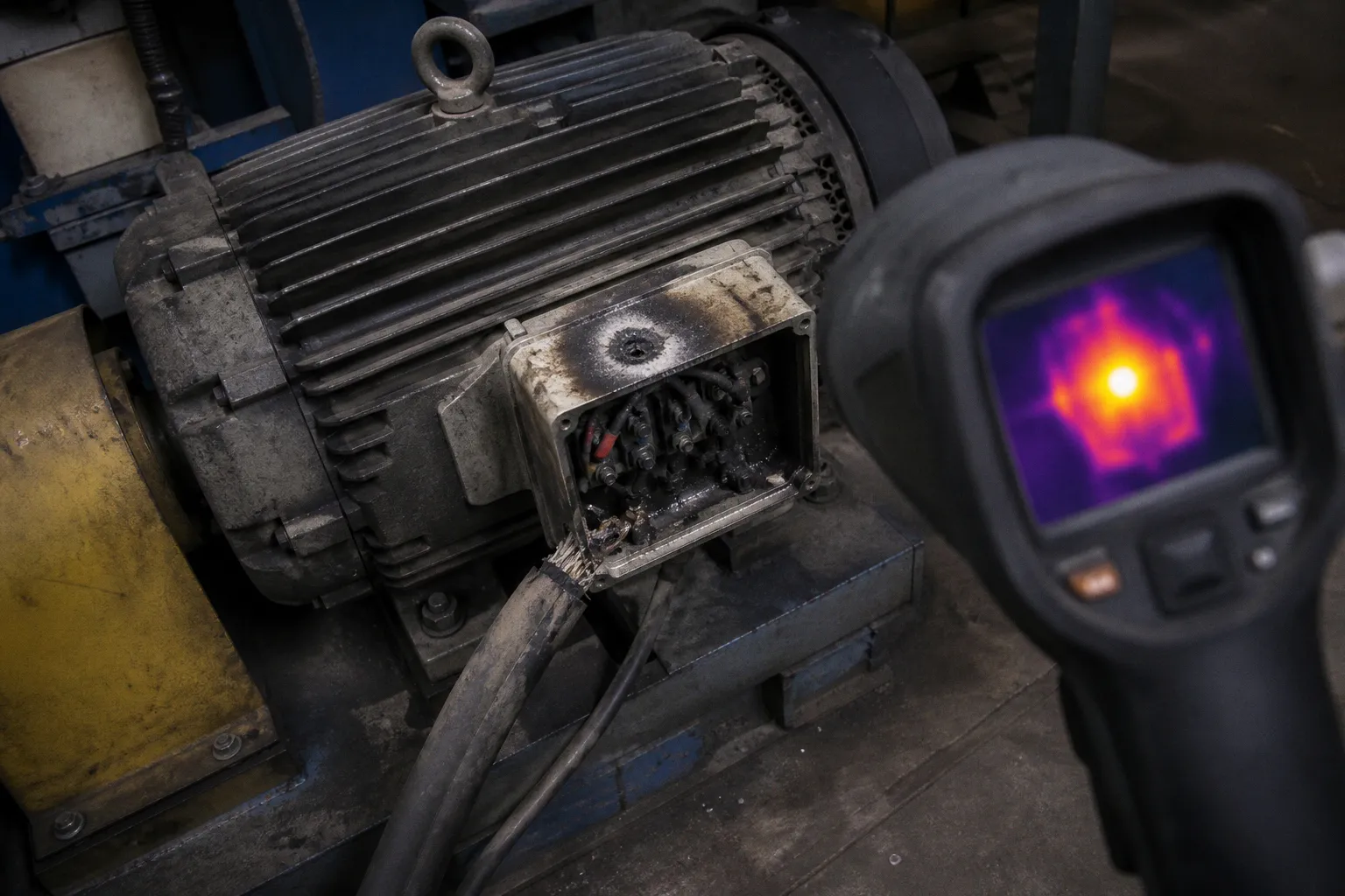
VFD Harmonic Distortion: Hidden Costs of Poor Power Quality
For a six-pulse drive with little or no internal impedance, ABB has published measurements in the range of approximately 80–120% total harmonic current distortion. Other research and field data place a more typical six-pulse-drive range closer to 30–35% under defined operating conditions.
Those figures are not interchangeable. A drive with no external line reactor may still contain internal impedance, and the distortion measured at the drive terminals is not the same quantity as distortion measured at the facility’s point of common coupling. Treating the highest published value as the universal performance of every six-pulse drive is just as misleading as assuming that a moderate terminal THDi automatically guarantees acceptable power quality throughout the plant.
The problem is structural. VFDs are nonlinear loads. They draw current in pulses rather than in smooth sinusoids. That pulsed current waveform decomposes into a fundamental frequency component plus a series of integer-multiple harmonics — and those harmonics interact with the facility’s electrical impedance in ways that are predictable, measurable, and avoidable if the engineer addresses them during design rather than after commissioning.
The cost rarely appears as a separate line item on a VFD purchase order. Depending on the installation, it can emerge as transformer heating, shortened capacitor life, nuisance trips on sensitive controls, reduced capacity in existing distribution equipment, or a utility charge associated with poor power factor. None of those outcomes is automatic in every plant. They become credible risks when the drive population, feeder impedance, capacitor configuration, and utility requirements create the conditions for them.
This article maps the distortion mechanism, quantifies the downstream consequences, clarifies what IEEE 519-2022 actually requires, and compares mitigation strategies on performance and cost. The goal is not to select the most expensive drive topology by default. It is to specify a drive package with a defensible harmonic budget.
The Physics of Nonlinear Loads: Why VFDs Distort Power
Every VFD front end contains a rectifier that converts incoming AC to DC. The DC bus then feeds the inverter stage, which synthesizes a variable-frequency output for the motor. The inverter controls motor speed and torque, but the rectifier is the principal source of input-current harmonics in a conventional drive.
A six-pulse rectifier — the standard three-phase bridge — draws current from the supply in six discrete pulses per cycle. The resulting input current waveform is not sinusoidal. Fourier analysis decomposes it into a fundamental component and harmonic components following the relationship:
h = kq ± 1
Here, q is the pulse number and k is a positive integer. For a six-pulse rectifier, the characteristic harmonic orders are the 5th, 7th, 11th, 13th, and higher orders. The 5th and 7th harmonics usually carry the largest current magnitudes and are therefore the first concern in a conventional installation.
The waveform at the terminals depends on more than the rectifier itself. A line reactor, DC-link choke, transformer impedance, cable length, source short-circuit capacity, and drive loading all affect the measured result. A drive operating near full load on a stiff source will not necessarily show the same THDi as the same model operating lightly loaded on a high-impedance feeder.
That is why a drive catalogue value is useful but incomplete. It describes a device under stated conditions. It does not describe the harmonic voltage that will appear at a remote panel, the current distortion at the service entrance, or the interaction between several drives and a capacitor bank.
Current distortion becomes voltage distortion through impedance
The facility’s electrical system does not absorb harmonic current without consequence. Harmonic current flowing through transformer windings, cables, busbars, and other system impedance produces harmonic voltage at each node. In simplified form, the relationship is:
Vh = Ih × Zh
The harmonic voltage at a given point depends on the harmonic current, Ih, and the system impedance at that harmonic frequency, Zh. Both are location-dependent. The impedance seen by a drive at its input terminals is not necessarily the impedance seen at the PCC, and the impedance changes with frequency.
This produces two important design consequences.
First, a drive can have relatively high input-current THDi while the facility still meets its PCC target if the drive is a small part of a large installation supplied by a stiff utility source. The distorted current is diluted when demand distortion is calculated against the facility’s total demand current.
Second, several individually acceptable drives can create an unacceptable system condition when they share a relatively weak feeder. Their harmonic currents add according to phase relationships and operating conditions, while the resulting voltage distortion is shaped by the complete network.
The system therefore needs to be studied as a system. A drive specification sheet cannot substitute for a short-circuit calculation, a load inventory, or a harmonic load-flow model.
Quantifying the Impact: From Transformer Overheating to Resonance Risks
Harmonic currents create risk through three connected mechanisms: additional heating, resonance, and voltage waveform distortion. The severity depends on the magnitude and duration of the harmonic current, the design of the equipment, and the facility’s electrical topology.
Heating and losses
Transformer and conductor losses are not determined solely by the fundamental current. Harmonic current increases resistive and stray losses, while higher-frequency components can produce disproportionate eddy-current losses in transformer windings and structural parts. The 5th harmonic on a 60 Hz system is 300 Hz; the 7th is 420 Hz. These components do not carry the same heating effect as the fundamental component.
A transformer carrying a heavily distorted load may therefore run hotter than its kVA reading suggests. The usable capacity of the transformer can be reduced, particularly where the unit was selected without accounting for nonlinear loads. Motors connected to a distorted voltage supply may also experience additional losses, torque pulsation, vibration, or temperature rise. The exact effect varies with motor design, loading, supply distortion, and the balance of the three-phase system.
The practical mistake is to treat a transformer’s nameplate rating as a complete statement of its available capacity. In a plant with a large VFD population, the relevant question is not simply whether the connected load fits within the kVA rating. It is whether the transformer can carry the actual current spectrum without excessive temperature rise or unacceptable voltage distortion.
Resonance and capacitor-bank failures
Power-factor-correction capacitors create a second layer of risk. Capacitors are installed to reduce reactive power demand, improve displacement power factor, or avoid charges under a particular utility tariff. They also present relatively low impedance to higher-frequency currents.
When the inductive reactance of the supply system and the capacitive reactance of the correction bank align near a characteristic harmonic frequency, a resonant circuit can form. At or near resonance, harmonic currents may circulate between the system inductance and the capacitors. The result can be amplified current or voltage at the capacitor terminals, even when the originating VFD appears to be operating normally.
Possible outcomes include capacitor fuse operation, overheating, premature capacitor failure, and elevated voltage distortion on the bus. In a severe case, the resonance can affect other connected equipment. But the presence of capacitors does not mean failure is inevitable. Detuned reactors, proper bank design, switching controls, and a harmonic study can reduce the risk substantially.
The important point is that a power-factor bank cannot be evaluated independently from the nonlinear loads it serves. A capacitor supplier’s rating and a VFD supplier’s rating may each be correct while the combined installation remains poorly coordinated.
Voltage distortion at the PCC
When harmonic current flows through the supply impedance, it creates voltage distortion at the point of common coupling. The PCC is the electrical boundary between the facility and the utility, commonly associated with the service entrance or another agreed metering and interconnection point.
Voltage distortion at this location matters because other customers may share the upstream feeder. The utility is concerned not only with the current waveform produced by one drive, but with the effect of the customer’s aggregate load on the common electrical system.
This is where the distinction between THDi and TDD becomes operationally important:
- THDi describes current distortion relative to the fundamental current of the equipment or load being measured.
- TDD describes demand distortion relative to the facility’s maximum demand current at the relevant point.
- PCC voltage distortion describes the voltage waveform at the utility-facing boundary.
A low THDi number at one drive terminal is not proof of compliance at the PCC. Conversely, a high terminal THDi number does not by itself establish a violation at the service entrance. The network between those two points determines how the current becomes voltage distortion.
The less visible cost pathways
Unmanaged harmonics can affect the maintenance and operations ledger in several ways:
- Transformer and switchgear temperature rise can reduce available capacity or accelerate component aging.
- Power-factor-correction capacitors can experience higher current stress or resonance-related faults.
- Sensitive PLCs, instrumentation, UPS systems, and control power supplies may be more vulnerable to voltage disturbances and overvoltage trips.
- Existing feeders may have less practical capacity than their fundamental-current calculation suggests.
- Motors and other equipment can experience additional losses or torque ripple.
- Utility charges may increase where the tariff or interconnection agreement accounts for power factor or distortion-related performance.
These are possible consequences, not a guaranteed sequence of events. Their timing is also site-specific. A plant with a stiff supply, modest VFD loading, no capacitor bank on the affected bus, and conservative transformer sizing may operate for years without a visible harmonic-related failure. Another facility with a weak feeder and a large cluster of drives may begin troubleshooting nuisance trips soon after expansion.
Harmonic distortion is not a drive specification problem alone. It is a system-impedance problem, and the cost appears wherever the electrical design has left no margin.
Navigating IEEE 519-2022: Setting Realistic Distortion Goals at the PCC
IEEE 519-2022, published on August 5, 2022, is the current revision of the IEEE recommended practice for harmonic control in electric power systems. It is not automatically a law or a universal equipment code. Its limits and design goals are commonly incorporated into project specifications, utility interconnection requirements, and engineering contracts, so the applicable project documents must be read alongside the standard.
The critical distinction is the measurement location. IEEE 519 places its principal harmonic objectives at the user’s point of common coupling. It does not impose one universal current-distortion limit at every internal panel, bus, or drive terminal.
That distinction changes how a drive package should be specified. A six-pulse drive may show roughly 30–35% current THDi under a stated operating condition, while the facility’s PCC TDD remains within the project target because the drive represents only a portion of total demand and the source is relatively stiff. A drive with little internal impedance may produce a much higher terminal value — published figures can reach approximately 80–120% — but the PCC result still depends on the rest of the network. The two statements describe different configurations and different measurement contexts.
The standard’s current-distortion framework also uses the ratio of the facility’s short-circuit current, Isc, to its maximum demand load current, IL. A higher Isc/IL ratio indicates a stiffer supply relative to the facility load. Such a system generally has more ability to absorb harmonic current without developing the same level of voltage distortion. A lower ratio indicates a weaker supply or a larger load relative to the available fault current, and the applicable current-injection limits are correspondingly more restrictive.
The engineering workflow should therefore begin at the PCC, not at the drive catalogue.
1. Establish the contractual and utility-defined PCC location.
2. Obtain the available short-circuit data and confirm the facility’s maximum demand basis.
3. Calculate the applicable Isc/IL ratio.
4. Identify the voltage class and the relevant IEEE 519-2022 current-distortion criteria.
5. Build the proposed load model, including drives, transformers, capacitors, UPS equipment, and other nonlinear loads.
6. Run a harmonic load-flow study for credible operating cases.
7. Select mitigation based on the predicted PCC result, not solely on the THDi value printed on a drive data sheet.
8. Define commissioning measurements, operating cases, and acceptance criteria before equipment is energized.
The operating cases deserve attention. A plant may look compliant at full production while exceeding the target during a lightly loaded condition, when a capacitor bank remains connected and the system resonance shifts. It may also show different results when only one large pump is running, when several drives accelerate simultaneously, or when a standby generator is supplying the bus.
A harmonic study should therefore examine the modes that matter operationally, not just one nominal snapshot. The model should also reflect the actual impedance of transformers, cables, reactors, and filters. A generic “typical” source impedance can produce a tidy report and a poor design.
Comparative Mitigation Strategies: From Line Reactors to Active Front-Ends
There is no universal best mitigation device. The right choice depends on the required PCC performance, the number and size of drives, load diversity, operating profile, available space, maintenance capability, and the existing electrical topology.
DC-link chokes and AC line reactors
An AC line reactor, often specified around 3–5% impedance, adds impedance between the supply and the drive. A DC-link choke performs a related function in the DC portion of the drive. Both approaches reduce the sharpness of the input current pulses and can lower peak current and harmonic content.
ABB’s published comparisons show a six-pulse drive without internal impedance at approximately 80% THDi in one configuration, with values reaching approximately 120% in some designs or operating conditions. Adding an AC line reactor or DC-link choke brings the published result into approximately the 35–50% range in the cited comparison. Other six-pulse-drive data report typical values around 30–35%, which illustrates why the configuration and test conditions must be stated with the number.
This is usually the first mitigation step because reactors are comparatively simple, available for many drive frames, and useful for more than harmonics. They can also reduce current notching and help limit transient stress. They do not, however, turn a conventional six-pulse front end into a low-harmonic drive. If the facility has many drives or a weak PCC, the remaining distortion may still require bus-level or drive-level mitigation.
Passive filters
Passive filters use inductors and capacitors to attenuate selected harmonic components. They may be installed at an individual drive or at a common distribution bus. A properly designed filter can deliver much lower input-current distortion than a reactor alone; published passive-filter drive packages commonly target approximately 5% THDi at the drive input under specified conditions.
The limitation is that passive filters are tied to the electrical system in which they are installed. Their performance depends on tuning, load range, source impedance, and the presence of other capacitive or inductive equipment. A filter designed around one network model may not behave the same way after a transformer is replaced, a feeder is extended, or a capacitor bank is switched.
Passive filters also need to be coordinated with the plant’s power-factor strategy. Adding capacitance without studying resonance can replace one power-quality problem with another. Protection, fusing, thermal performance, and access for inspection all belong in the design review.
Pulse multiplication
A 12-pulse rectifier uses a phase-shifting transformer to feed two six-pulse bridges with a 30-degree phase displacement. Under balanced operating conditions, the arrangement cancels characteristic 5th and 7th harmonic currents at the common supply. Rockwell Automation comparison data places typical 12-pulse current THDi in the 6.5–9.5% range, while Danfoss specifies approximately 12% THDi at full load under ideal grid conditions for a particular 12-pulse configuration.
An 18-pulse arrangement extends the cancellation scheme and can bring current THDi into the approximately 4.5–5% range under appropriate conditions. The performance depends on balanced bridge currents and matched transformer impedances. Unequal loading, transformer tolerances, aging, and temperature can reduce the theoretical cancellation.
The tradeoff is physical as much as electrical. A phase-shifting transformer adds cost, weight, losses, footprint, and installation complexity. It may be entirely reasonable for a large pump station or a central drive lineup, but awkward for a distributed group of small drives.
Active harmonic filters
An active harmonic filter is a separate power-electronic device connected to a distribution bus. It measures the harmonic current and injects a compensating current intended to cancel it. Unlike a filter attached to one drive, an AHF can address multiple nonlinear loads on the same bus, including drives from different manufacturers and other rectifier-based equipment.
This bus-level approach is useful where the load mix changes over time. It can also be more economical than replacing every existing drive when the primary problem is concentrated at one switchboard or feeder.
The performance must still be sized against the actual spectrum and operating range. The filter has a finite compensation current, draws energy for switching and control, and requires appropriate protection and cooling. If the plant expands beyond the original harmonic budget, the installed AHF may no longer have sufficient capacity.
Active front-end drives
An active front end replaces the conventional diode rectifier with a controlled power-electronic input stage. With an appropriate input filter and control strategy, the drive can draw current much closer to a sinusoidal waveform. Typical AFE drives achieve approximately 3–5% THDi under stated conditions, while ABB’s latest-generation ultra-low-harmonic drive is specified below 3% THDi in its published operating envelope.
AFEs can also return regenerative energy to the supply. That feature may justify the additional complexity in hoists, centrifuges, test stands, elevators, and other applications with frequent braking or overrunning loads. It is less compelling for a simple fan or pump that rarely regenerates.
The penalties include higher initial drive cost, switching losses, a more complex input filter, greater control complexity, and additional requirements for commissioning and maintenance. An AFE is a strong technical solution when the harmonic target is tight or regeneration has value. It is not automatically the lowest-total-cost solution for every motor.
Comparing the options honestly
| Strategy | Typical input-current performance | Relative cost position | Where it fits | Main limitation |
|---|---|---|---|---|
| Six-pulse drive with little or no internal impedance | Published values can be approximately 80–120% THDi in some configurations; other six-pulse data show roughly 30–35% under stated conditions | Baseline drive cost | Applications with sufficient source strength and acceptable PCC study results | High and highly configuration-dependent distortion |
| AC line reactor or DC-link choke | Often approximately 35–50% in published comparisons; actual result depends on drive and operating point | Low incremental cost | Individual-drive protection and first-stage harmonic reduction | May remain inadequate for a weak PCC or large drive population |
| Passive filter package | Approximately 5% THDi in published drive packages under defined conditions | Moderate | Projects requiring substantial attenuation at selected harmonic orders | Tuning, resonance, reactive power, and changing system impedance |
| 12-pulse rectifier | Approximately 6.5–12% in cited configurations | Moderate to high | Larger drives where a phase-shifting transformer is acceptable | Transformer size, losses, footprint, and balance requirements |
| 18-pulse rectifier | Approximately 4.5–5% under suitable conditions | High | Large, centralized drive systems with stringent distortion goals | Larger transformer and sensitivity to bridge-current matching |
| Active harmonic filter | Adaptive bus-level compensation; performance depends on rating and harmonic spectrum | High | Multiple diverse nonlinear loads sharing a bus | Finite compensation capacity and power consumption |
| Active front-end drive | Typically approximately 3–5%; below 3% for some latest-generation products under stated conditions | Highest among the listed drive options | Tight harmonic targets, regeneration, or new high-performance installations | Higher cost, switching losses, input-filter complexity |
The table is a comparison of drive-side or filter-side performance, not a promise of PCC compliance. The final result still depends on the network model and the way the equipment is operated.
The correct strategy is often a combination. In a facility with many distributed drives, line reactors on individual units plus an active harmonic filter at the common bus may meet the PCC target at lower installed cost than replacing every drive with an AFE. In a new high-capacity pumping installation with a central motor lineup, 12-pulse, 18-pulse, or AFE equipment may be easier to coordinate than a collection of small corrective devices.
Economic Realities of Power Quality: Analyzing Retrofit and Infrastructure Costs
Harmonic mitigation costs money. So does ignoring harmonics. The difficult part is that the two costs are not expressed in the same budget.
The DOE Better Buildings case study of a 139,000-square-foot data-center retrofit provides a useful cost snapshot. The total project cost was $750,000, including $342,000 for variable-speed-drive equipment, $69,000 for installation labor, and $339,000 for harmonic-mitigating transformers. The transformer portion represented 45% of the total project cost in that specific case — not 45% of total drive-system cost.
That distinction matters. The case study does not establish a universal ratio for VFD projects, nor does it show that harmonic mitigation will normally consume nearly half of a drive package budget. It demonstrates that harmonic control can become a first-order infrastructure expense when it is added to an existing facility with constrained distribution equipment.
Actual cost depends on the project configuration:
- The number, rating, and duty cycle of the drives determine the amount and variability of harmonic current.
- Existing transformer capacity and impedance determine whether the distribution system has enough margin.
- Feeder length and conductor size affect the impedance seen by the loads.
- Utility PCC requirements determine how much reduction is actually necessary.
- Capacitor banks, UPS systems, generators, and other nonlinear loads can alter the harmonic and resonance model.
- Available space, access, ventilation, and shutdown requirements can dominate the installation budget.
- A filter that looks inexpensive at the equipment level may require new protection, switchgear, wiring, controls, or commissioning time.
The cost of inaction
The cost of poor power quality is difficult to isolate because it is distributed across several departments. A capacitor replacement may be recorded as maintenance. A PLC trip may be blamed on software. A transformer derating may appear as a capacity constraint. A production interruption may be assigned to the process rather than to the electrical supply.
A power-quality audit can connect those events to a common mechanism. The potential cost categories include:
- reduced transformer or feeder capacity;
- additional losses and temperature rise;
- shortened capacitor or switchgear life;
- nuisance trips and troubleshooting labor;
- production downtime;
- replacement of equipment that failed under repeated electrical stress;
- utility charges associated with the applicable power-factor or interconnection arrangement.
There is no defensible universal dollar value for these effects. A lightly loaded plant and a continuously operating process facility do not have the same exposure. The duty cycle, equipment criticality, spare capacity, and utility tariff all change the result.
What can be said with confidence is that the costs are configuration-dependent and often difficult to attribute after the fact. That is precisely why harmonic analysis belongs in the design phase.
Design-phase versus retrofit economics
Adding a reactor, selecting a low-harmonic drive, changing the transformer arrangement, or reserving space for a bus filter during design is usually easier than making the same change after the equipment is installed. The advantage is not a universal percentage saving. It is the ability to coordinate the electrical package before cable routes, protection settings, switchgear ratings, and operating procedures have been fixed.
A retrofit may require a shutdown, temporary generation, new feeder work, replacement transformers, revised protection, or access through an operating production area. In other cases, a bus-level active filter can solve the problem without replacing the installed drives. The answer must come from the study rather than from a generic claim that one technology is always cheaper.
A sensible budget should separate at least four elements:
1. Equipment cost: reactors, filters, transformers, AFE drives, capacitors, and associated protection.
2. Installation cost: labor, cabling, structural work, ventilation, commissioning, and planned outages.
3. Study and verification cost: modeling, measurements, harmonic load flow, resonance checks, and acceptance testing.
4. Operational exposure: downtime, reduced capacity, maintenance interventions, and the value of lost production if the facility operates outside its power-quality margin.
The third category is easy to omit because it does not produce a large piece of hardware. It is also the category that prevents expensive equipment from being selected against the wrong measurement point.
Building a Defensible Harmonic Budget
A harmonic budget should identify the source, the path, the boundary, and the acceptance condition. “The drives have reactors” is not a budget. It says what one component contains, but not what the utility will see.
For each major drive group, the design record should state:
- drive topology and pulse number;
- whether impedance is internal, external, or both;
- rated power and expected operating range;
- input-current THDi test conditions;
- transformer rating and impedance;
- feeder configuration and length;
- capacitor-bank arrangement, if present;
- other nonlinear loads on the same bus;
- the modeled PCC location;
- expected PCC TDD and voltage distortion for relevant operating cases;
- selected mitigation and its available margin;
- commissioning measurements and corrective-action thresholds.
The operating cases should reflect how the facility actually runs. A pump system with several motors may have one harmonic profile at maximum flow and another when only a single large pump is operating. A process line may create the worst condition during startup or low-load operation. A standby generator can present a substantially different source impedance from the utility supply.
Measurement is the final check. Record the fundamental current, harmonic spectrum, voltage distortion, capacitor current, and operating state at the agreed locations. Measurements should be taken at the PCC and, where useful, at the major internal buses. If the acceptance requirement is stated at the PCC, testing only at individual drive terminals answers the wrong question.
The same discipline applies when diagnosing an existing installation. Before replacing drives, measure the network under multiple load conditions. Check whether the problem is current distortion, voltage distortion, resonance, source switching, grounding, or a combination of issues. A drive may be blamed for a PLC fault that is actually caused by a poorly coordinated capacitor bank or a weak control-power circuit.
The practical position
Industrial VFD harmonic distortion mitigation is not a contest to achieve the lowest possible THDi at the drive terminals. It is an engineering decision about the quality of power delivered to the entire facility and, at the PCC, to the upstream network.
A conventional six-pulse drive can be an appropriate choice when its harmonic contribution is evaluated against the available short-circuit capacity, total facility demand, transformer design, and utility requirements. A reactor or DC-link choke may provide enough margin. A passive filter, pulse-multiplication transformer, active harmonic filter, or AFE may be justified where the source is weak, the drive population is large, regeneration is valuable, or the PCC target is tight.
The expensive mistake is not selecting the least sophisticated topology. It is selecting any topology without knowing the system in which it will operate.
Model the PCC. State the measurement basis. Include the capacitor banks and operating modes. Treat published THDi figures as configuration-specific data, not universal promises. Then price the mitigation against both the installed infrastructure and the operational consequences of leaving the problem unresolved.
That is how power quality becomes part of the design rather than a maintenance surprise.