Frequency converter commissioning errors causing hidden plant downtime
Frequency converter commissioning errors plant downtime rarely begin with a dramatic drive failure.
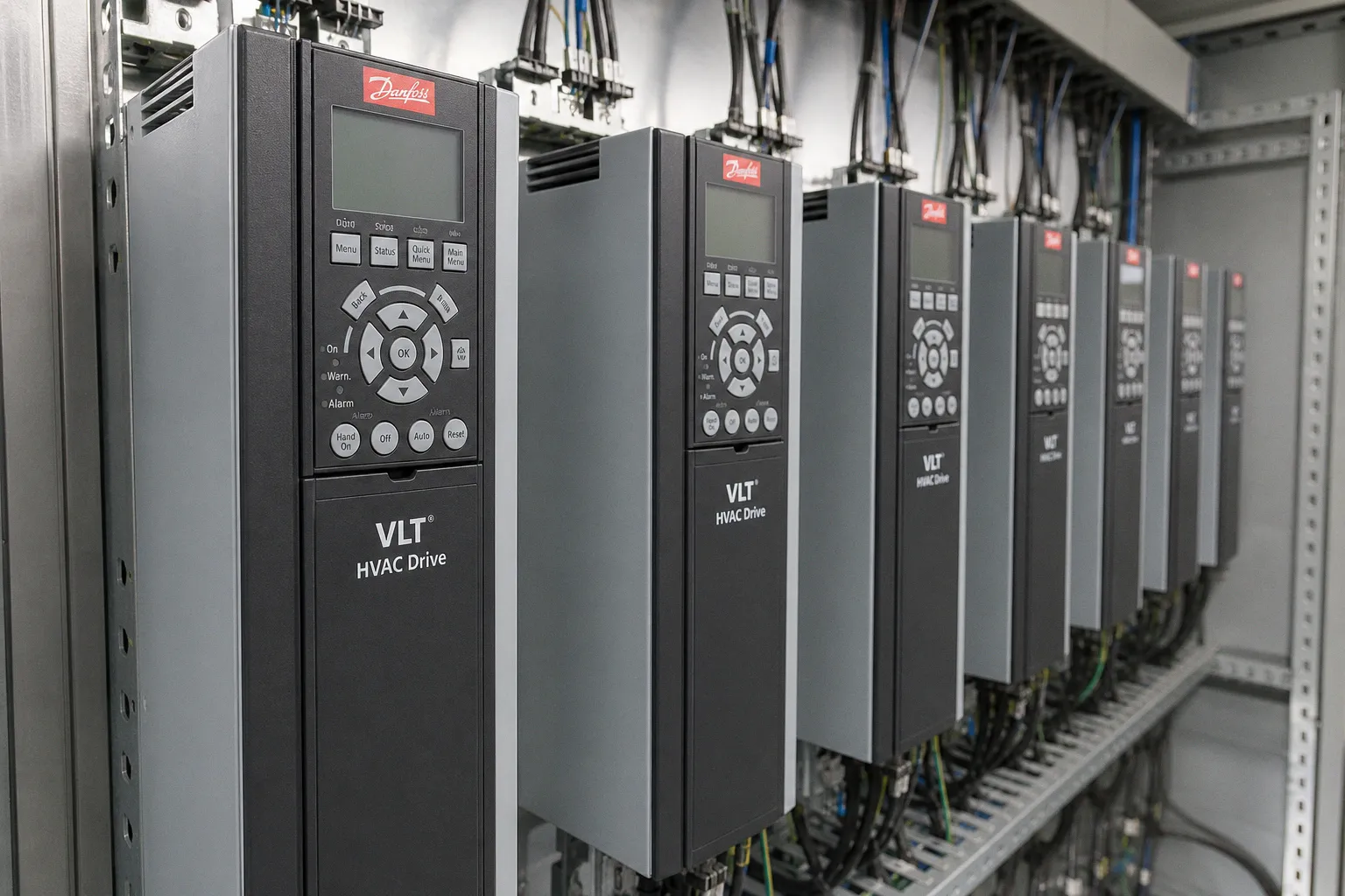
More often, the system reaches production, runs for several shifts, then stops on a condition introduced during startup: a thermal model built from wrong nameplate data, a fieldbus timeout configured as a trip, a ramp that exceeds available process torque, or no-flow logic that interprets normal transients as a dry-pump event.
The visible symptom is a stopped motor. The root cause is usually a design decision made during commissioning without enough context from the motor, pump curve, control network, or operating sequence. This is why inverter installation troubleshooting often becomes inefficient. Maintenance teams inspect cables and replace components while the actual defect remains stored in a parameter group.
A frequency converter is not a generic speed dial. It is a control system with assumptions. Commissioning defines those assumptions. Wrong inputs create hidden latency between cause and diagnosis, increase operator cognitive load, and raise the error rate during recovery.
Motor nameplate data is control-model input, not administration
Motor data entry is routinely treated as a low-risk startup task. It is not. For a Danfoss VLT HVAC Drive, quick setup requires motor power, voltage, frequency, current, and nominal speed from the motor nameplate. These values support torque calculation, thermal protection, and automatic motor compensation.
A single incorrect field can create different failure modes:
- Nominal current entered too low can make the thermal model restrictive. The drive may trip during normal load peaks even when the motor and pump are mechanically healthy.
- Nominal current entered too high weakens the usefulness of electronic motor protection. A real overload may remain undetected for longer than intended.
- Incorrect nominal speed degrades slip and speed compensation. The requested frequency may no longer produce the expected shaft speed.
- Motor voltage and frequency mismatches distort the drive’s voltage-to-frequency relationship. Torque capability becomes less predictable, especially during acceleration.
- Motor power entered from the converter rating rather than the motor plate creates a false model from the first power-up.
The data-entry ranges available in a drive interface can be broad. The cited Danfoss documentation permits entries from 0.09 to 3,000 kW, 10 to 1,000 V, and 0.10 to 10,000 A. Broad input ranges reduce interface friction. They do not validate that the entered values belong to the connected machine.
The commissioning record should therefore capture the physical nameplate, not merely the final parameters. A photo of the motor plate, terminal-box connection configuration, cable length, motor identifier, and drive identifier provides a traceable baseline. Without it, a later replacement motor can inherit a parameter set intended for a different frame size, winding voltage, or rated current.
Automatic Motor Adaptation is often run without verifying its preconditions
Automatic Motor Adaptation, commonly abbreviated as AMA, is useful because it identifies electrical motor characteristics rather than relying entirely on generic defaults. It is also a recurring source of motor drive startup failures because technicians run it as a ritual instead of a controlled measurement.
A complete Danfoss AMA measures stator resistance, rotor resistance, stator and rotor leakage reactance, and main reactance. A reduced AMA measures stator resistance only. This distinction matters. If an LC filter sits between converter and motor, the documented requirement is reduced AMA, not a complete routine. Using the wrong method changes the quality and applicability of the measured model.
AMA failures are frequently linked to two setup defects:
1. Incorrect motor nameplate data was entered before the routine started.
2. The converter and motor ratings are too far apart for the measurement to be valid.
Danfoss also specifies a minimum condition: rated motor current must be at least 35% of the converter’s rated output current for AMA to run. This is an architecture constraint, not a nuisance alarm. An oversized converter can reduce the available measurement resolution for a small motor.
Timing also matters operationally. AMA may take up to 10 minutes in operating instructions; design guidance indicates that large motors can require more than 15 minutes. A commissioning plan that treats this as a two-minute task creates pressure to interrupt the procedure, bypass it, or accept an incomplete result without documenting the limitation.
A drive can only control the motor model it has been given. Wrong plate data is not a minor setup defect; it is a wrong control model.
The following distinction is useful when diagnosing apparent tuning issues after startup:
| Observation | Likely commissioning defect | Appropriate response |
|---|---|---|
| Trip during normal process loading | Motor current, thermal parameters, or torque limits do not match the actual motor/load | Verify motor plate data and mechanical load before changing protection thresholds |
| Unstable speed under changing load | Nominal speed or motor model is inaccurate; compensation may be wrong | Review entered speed data, motor connection, and AMA method |
| AMA cannot complete | Motor/converter sizing relationship or input data is invalid | Confirm rated current, converter output rating, wiring topology, and filter arrangement |
| New replacement motor behaves differently on an existing drive | Old parameters were retained without comparison to the new motor | Recommission the motor model; do not assume equivalent kW ratings mean equivalent data |
| Repeated resets restore operation temporarily | Protection is reporting a real discrepancy, but the parameter baseline is unverified | Stop reset-driven recovery and audit the commissioning record |
The throughput problem here is not just the stopped asset. It is the recovery pattern. Each unnecessary reset adds operator activity but contributes no diagnostic evidence. Over time, the plant normalizes unstable behavior.
Communication timeout settings can convert a network disturbance into a process trip
A frequency converter has at least two control paths: local drive logic and external commands. In a networked installation, the PLC, remote I/O, SCADA layer, safety architecture, and fieldbus all influence what the drive interprets as a valid command state.
A control-word timeout exists to define what happens when communication disappears. That is a necessary function. The failure occurs when its action is selected without regard to process dynamics and network behavior.
For Danfoss drives, Alarm 17, “Control word timeout,” indicates that communication to the converter has been lost. If the timeout function is configured as “Stop and Trip,” the drive ramps down and then trips. Recovery then requires a reset sequence in addition to restoring communications.
This may be appropriate for a machine where any loss of supervisory control must produce a faulted state. It may be unsuitable for a pumping system where a brief switchover, cable disturbance, managed network event, or PLC restart should lead to a defined fallback condition rather than a hard trip. The correct behavior depends on the risk analysis, hydraulic process, autonomous controls, and restart policy. There is no universal timeout value.
The common VFD parameter setup mistake is to increase timeout duration simply because timeout trips are inconvenient. That reduces visible nuisance alarms, but it can also hide a broken serial link, stale command state, or failed controller. The opposite mistake is equally damaging: using a short timeout with a trip action on a control network that has not been characterized for worst-case latency, switch recovery, or controller restart behavior.
Commissioning must identify four separate timings:
- Network update interval: how often the controller sends valid process data.
- Network recovery behavior: what occurs during managed switch recovery, PLC restart, or redundant-path failover.
- Drive timeout threshold: how long the drive waits before declaring control communication lost.
- Process-safe response time: how quickly the pump, fan, valve, or conveyor must enter a controlled state to avoid process damage.
These are not interchangeable numbers. A fieldbus cycle time is not a safety response time. A PLC scan time is not proof of network availability. A drive’s timeout is not an alarm-delay setting to be tuned by frustration.
A useful startup test deliberately removes communications under controlled conditions. The test should confirm the actual drive response, PLC alarm behavior, HMI indication, restart inhibit logic, and process consequence. If the system response is unknown until the first cable fault, the commissioning was incomplete.
Fault taxonomy reduces diagnostic latency
Drive documentation lists many alarm and trip categories: inverter overload, motor thermal overload, overcurrent, ground fault, short circuit, overtemperature, missing motor phase, mains failure, phase imbalance, and fieldbus fault. These categories are not interchangeable. Yet many control-room interfaces collapse them into “VFD fault.”
That aggregation lowers screen complexity but raises cognitive load during recovery. It removes the distinction between a network-state problem, a motor-circuit problem, and a mechanical process problem.
A practical fault model should preserve at least these fields:
- active drive warning or trip text;
- event timestamp from the drive and from the PLC;
- commanded speed and actual speed at the event;
- motor current and DC bus condition where available;
- fieldbus state;
- permissive and interlock states;
- process values such as pressure, flow, level, or valve position;
- reset source and number of reset attempts.
This is not an argument for collecting every available tag. It is an argument for retaining the minimum evidence required to separate root causes. Data that cannot change a diagnostic decision adds interface noise.
Ramp limits are mechanical constraints expressed as time
Acceleration and deceleration settings are frequently copied from a prior project, retained from factory defaults, or adjusted until the drive stops tripping. None of these methods establishes whether the ramp fits the motor, driven load, pipework, process, or stopping requirement.
Acceleration requires torque. For a pump system, the motor must accelerate rotating inertia while moving the hydraulic system toward its operating point. If the requested ramp is too aggressive, current rises and the converter may reach current limit or trip on overcurrent. Increasing current limit to force the ramp through is not a correction. It can shift stress from the control system into couplings, bearings, shafts, pipe supports, and the electrical supply.
Deceleration has its own failure mode. A load with significant inertia can return energy to the DC bus during rapid slowdown. The resulting overvoltage response depends on drive design, braking hardware, load characteristics, and configured protection behavior. A longer deceleration ramp may be necessary, but the final setting must still meet the process requirement. A water system may need a controlled slow stop to reduce pressure transients. A conveyor may need a defined stop distance. These are separate engineering problems.
The commissioning sequence should be explicit:
1. Establish the mechanical and process constraint first: permitted acceleration, permitted deceleration, allowable pressure change, and required stop behavior.
2. Start with conservative ramps that do not demand unnecessary torque or braking energy.
3. Trend current, speed, pressure, flow, and relevant vibration or torque indicators during controlled tests.
4. Compare the observed response with the intended operating envelope, including minimum and maximum speed.
5. Adjust one variable at a time. Document the reason, result, and final value.
6. Repeat the test after control handoff to the PLC or remote system, because command-source transitions can introduce different ramp behavior.
The weak pattern is parameter chasing: current limit up, ramp down, trip reset, repeat. It reduces immediate latency but leaves the load model unknown. The stronger pattern is to determine whether the trip follows commanded dynamics, actual mechanical resistance, hydraulic behavior, or an electrical defect.
No-flow logic and rotation checks need process context
Pump-protection logic is often installed with good intent and poor commissioning discipline. No-flow detection, dry-run protection, minimum-speed behavior, and sleep functions can prevent damage. They can also stop a healthy pump when the logic is configured around generic assumptions rather than the actual process.
In the Danfoss no-flow function, the default delay is 10 seconds and the configurable range is 1 to 600 seconds. If the selected no-flow action is alarm, the converter trips and the motor remains stopped until reset.
That configuration may be correct for one application and disruptive in another. Consider the conditions that can resemble no-flow during normal operation:
- a pump is ramping from rest and has not yet established stable differential pressure;
- a duty/standby sequence is transferring between pumps;
- a control valve is moving through a temporary restrictive position;
- a level-controlled system is approaching an empty basin or a low-demand period;
- a sensor is noisy, poorly scaled, or located where pressure does not represent actual flow;
- the pump curve and pipe system create a low-flow operating zone that is valid but short-lived.
The response is not to disable no-flow protection or extend the delay until alarms disappear. The response is to define what “no flow” means in this process. That definition may use power, differential pressure, flow transmitter input, speed threshold, valve status, tank level, elapsed time, or a combination of signals. The architecture should also distinguish a protective stop from an alarm requiring operator intervention.
A pump system with unreliable no-flow logic develops a predictable failure pattern: operators reset the drive, automatic restart repeats, and the HMI shows a generic fault. The system’s error rate rises because the interface does not explain whether it detected a dry condition, a sensor inconsistency, a closed discharge path, or a control-sequence conflict.
Rotation verification is a controlled test, not a production test
Motor rotation must be verified after installation and connection. This is basic, but the consequences can be hidden. A centrifugal pump rotating in the wrong direction may still turn smoothly, draw some current, and produce an abnormal process result rather than an immediate electrical fault.
Danfoss documentation warns that enabling the motor-rotation-check function can cause the motor to run in the wrong direction. That behavior is the point of the test: the drive must briefly establish actual rotation. It also means the test requires a safe mechanical and process condition. The pump, valves, connected equipment, and personnel exposure must be considered before command execution.
If rotation is wrong, phase conductors must not be swapped on an energized system. The documented procedure requires removing line power before interchanging two motor phase cables. This is not procedural formality. It separates a controlled electrical modification from live work around stored and supplied energy.
A rotation check performed after the system enters normal service is not verification. It is an uncontrolled process experiment.
Rotation verification should be recorded with the same discipline as motor data entry. The record should state the observed direction, verification method, process isolation condition, responsible technician, and any changes made at the motor terminals. This prevents a later maintenance event from reversing the correction without awareness of the original test.
Startup safety is not satisfied by a stop command
Commissioning creates pressure to restore operation quickly. That pressure produces one of the most serious category errors in industrial automation: treating a stop pushbutton, PLC stop bit, selector switch, or fieldbus command as energy isolation.
They are control devices. They are not energy-isolating devices.
Under OSHA 29 CFR 1910.147, servicing and maintenance involving possible unexpected energization, startup, or hazardous-energy release require an energy-control program and procedures that isolate the equipment from its energy source and render it inoperative. The distinction is direct. A drive can receive a start command from a remote system after a local stop command. Stored energy can remain in the DC bus. Connected equipment can create hydraulic, pneumatic, gravitational, or mechanical hazards even when motor torque is absent.
This affects commissioning work in practical ways:
- A technician checking motor terminals, changing phase order, or inspecting output wiring needs formal isolation, not a local stop condition.
- A drive reset does not prove the machine cannot restart from another command source.
- Hand-off-auto selectors must be evaluated as part of the command architecture, not treated as lockout devices.
- Remote start paths from PLC logic, SCADA commands, maintenance bypasses, and automatic duty rotation must be identified before testing.
- Commissioning procedures need a clear boundary between functional testing and maintenance intervention.
The control system should make state visible. If a drive is unavailable because of energy isolation, the HMI should not display it as a vague communications failure. If it is stopped by a process interlock, that should be separate from a drive trip. If it is healthy but inhibited by a remote permissive, the operator should see the source of inhibition.
This interface clarity has a measurable operational effect. It reduces time spent navigating ambiguous alarms and reduces incorrect reset attempts. It does not eliminate faults. It shortens the path from symptom to evidence.
Commissioning quality is visible in the first abnormal event
A stable startup is not proof that commissioning is complete. The relevant test is the first abnormal event: a dropped network packet sequence, a low-flow transient, a controlled power interruption, a pump transfer, an overload condition, or a motor replacement. If the system responds predictably, exposes the reason, and returns through a defined recovery path, the configuration has operational value.
If it stops with “drive fault” and requires a person to guess, the plant has inherited configuration debt.
Frequency converter commissioning errors are avoidable when the work is treated as system integration rather than parameter entry. The motor, converter, process, network, safety boundary, and operator interface all need a consistent model. The target is not the fewest alarms. The target is a fault response that is selective, diagnosable, and proportionate to the actual risk.
Use these design heuristics at startup:
- Record motor nameplate evidence and terminal configuration before entering drive data.
- Select complete or reduced motor adaptation according to the installed electrical topology, including output filters.
- Treat AMA failure as evidence. Do not bypass it before validating motor data and converter-to-motor sizing.
- Define communication-loss behavior from process risk and tested network recovery behavior, not from a generic timeout value.
- Test fieldbus loss, command-source transfer, restart behavior, and HMI messaging before handover.
- Tune acceleration and deceleration against actual load and process constraints; do not use protection-limit changes to conceal a mismatch.
- Configure no-flow and dry-run functions from validated process signals and operating transients.
- Verify rotation under controlled conditions, then isolate energy correctly before changing motor connections.
- Preserve alarm specificity from drive to HMI. Generic fault labels increase diagnostic latency.
- Separate stop commands from hazardous-energy isolation in both procedures and interface language.