Bearing failure analysis: a path to equipment reliability
More than 99% of roller bearings can reach their projected service life when load, speed, lubrication, mounting, and operating conditions remain within the intended envelope. Therefore, a failed bearing is usually not evidence of an unreliable product.
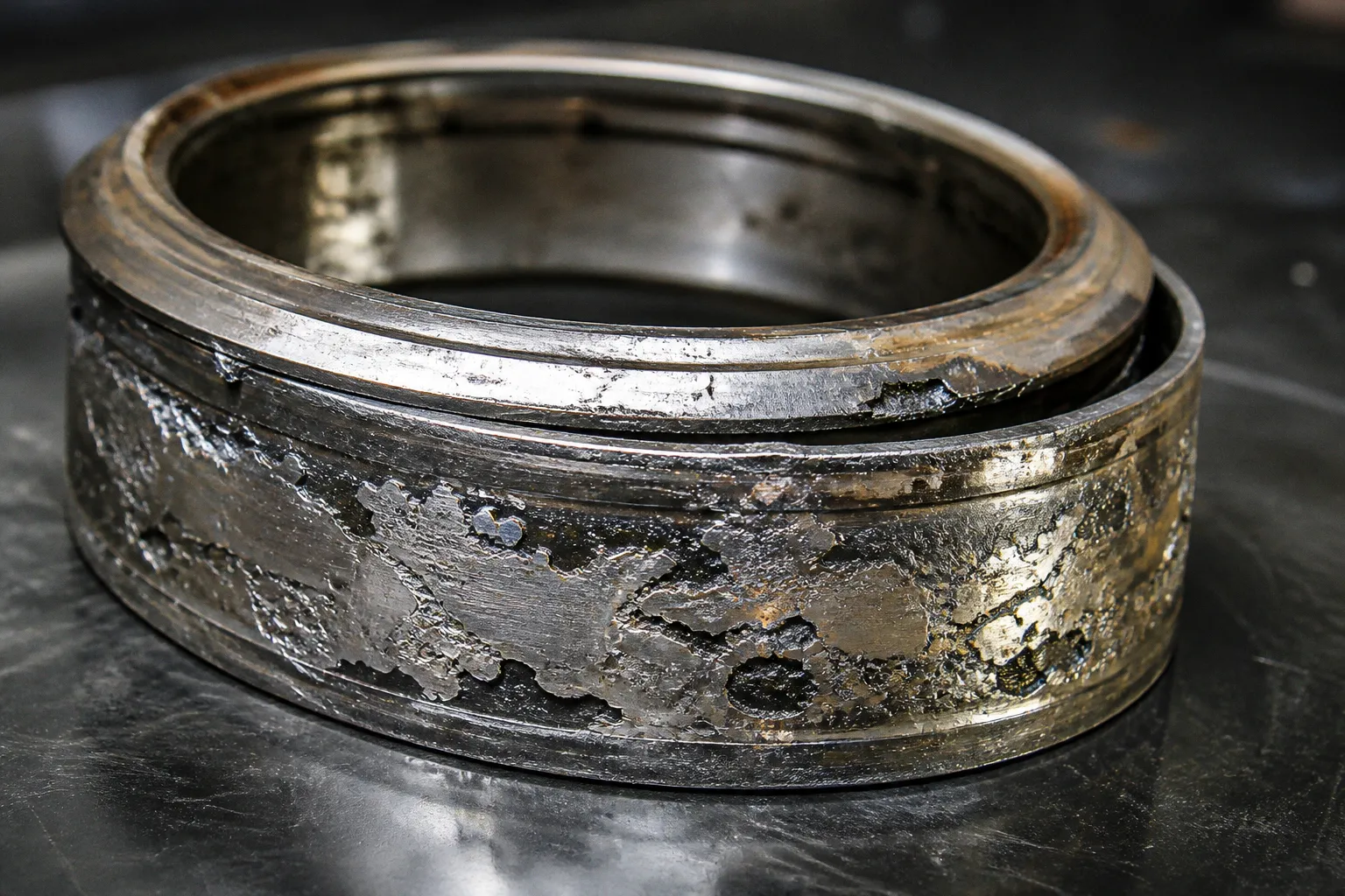
It is evidence of a system deviation.
The deviation may be mechanical, operational, environmental, or procedural. The visible damage is only the final output. A reliable investigation works backward from that output. It separates the damage mechanism from the initiating cause, then removes the condition that will otherwise destroy the replacement bearing in the same way.
Industrial bearing failure analysis steps are not complicated. They are sequential. The failure rate rises when teams skip the sequence, clean the evidence too early, or replace a component without examining the surrounding machine.
The useful starting point: failure is a system event
A bearing does not operate in isolation. It transfers radial and axial loads between a shaft, a housing, a rotating assembly, and a lubricant film. Its service life depends on the combined behavior of these elements.
A bearing can fail through fatigue even when the part was correctly manufactured. It can also fail through wear, corrosion, electrical erosion, plastic deformation, or fracture. These mechanisms leave different physical signatures. Treating every damaged bearing as a generic lubrication problem produces the wrong corrective action.
The investigation should begin before the bearing is removed. Capture the operating context while it still exists:
- Machine function and driven equipment.
- Bearing position and load direction.
- Rotational speed and duty cycle.
- Normal and abnormal temperature history.
- Recent changes to throughput, speed, process material, or operating sequence.
- Lubricant type, quantity, application method, and relubrication interval.
- Shaft and housing condition.
- Seal arrangement and contamination exposure.
- Mounting method and installation tools.
- Alignment records and coupling condition.
- Alarm history from vibration, temperature, ultrasound, or process monitoring.
This is not administrative overhead. It preserves causality. Once a bearing is removed, the relationship between the damage and the machine condition becomes harder to reconstruct. A cleaned component contains less evidence than a contaminated one. A replaced seal can conceal the entry path. A polished raceway can obscure the original surface pattern.
A replacement bearing is not a corrective action. It is only a new test of whether the original failure mechanism is still active.
The first decision is therefore not which bearing to order. It is whether the machine is ready to receive a new bearing without repeating the same loading, contamination, or lubrication error.
Categorizing damage with ISO 15243
ISO 15243 provides a practical classification framework for rolling bearing damage. The current framework groups failure modes into six primary categories:
1. Fatigue.
2. Wear.
3. Corrosion.
4. Electrical erosion.
5. Plastic deformation.
6. Fracture and cracking.
The categories reduce diagnostic ambiguity. They do not replace physical inspection or operating data. A single bearing may show multiple mechanisms. For example, contamination can create abrasive wear, weaken the lubricant film, and accelerate fatigue on the raceway. The visible result may be a mixed pattern rather than one clean category.
Fatigue
Fatigue is associated with repeated subsurface and surface stresses generated by rolling contact. Early damage may appear as localized flaking or spalling on a raceway or rolling element. The location and distribution matter.
A fatigue pattern concentrated in the loaded zone may be consistent with normal life progression or excessive load. A pattern displaced from the expected load zone can indicate misalignment, incorrect internal clearance, shaft deflection, or an abnormal load path.
The investigation should connect the spall geometry to:
- Applied load.
- Load direction.
- Rotation.
- Bearing arrangement.
- Internal clearance.
- Shaft and housing geometry.
- Lubrication film strength.
Fatigue should not be used as a final explanation by itself. It describes the damage mechanism. It does not establish why the contact stress exceeded the bearing’s usable operating envelope.
Wear
Wear removes or modifies material through sliding, abrasive particles, inadequate film separation, or repeated surface contact. Identifying bearing wear patterns requires examination of both the bearing and the lubricant.
Abrasive wear may produce dull, scratched, or polished surfaces. The pattern can indicate contamination ingress or debris generated elsewhere in the machine. Adhesive wear is associated with local material transfer and insufficient separation between contacting surfaces. Smearing may appear where sliding occurs at excessive speed, during rapid acceleration, under insufficient load, or with inadequate lubrication.
Wear analysis should include the adjacent components. A bearing may be the collector of debris rather than the source. Gear wear, seal damage, machining residue, degraded coatings, and corrosion products can all enter the rolling contact.
Corrosion
Corrosion can result from moisture, process chemicals, condensation, improper storage, or incompatible protective conditions. It can appear as staining, etching, pitting, or more extensive surface attack.
The location is a diagnostic variable. Corrosion distributed across exposed surfaces suggests an environmental or storage problem. Localized corrosion near a seal or housing interface points toward ingress. Repeated axial marks or evenly spaced depressions may indicate false brinelling or vibration during stationary periods rather than conventional chemical corrosion.
Corrosion also changes the future failure path. Surface damage creates stress concentrations. Once the machine returns to operation, those points can become origins for fatigue and spalling.
Electrical erosion
Electrical current passing through a bearing can create localized melting and surface damage. The source may be a motor, variable-frequency drive, grounding defect, or inadequate current path around the bearing.
Electrical erosion often requires more than a visual inspection. The investigation should examine grounding, shaft voltage, insulation arrangements, motor configuration, and the machine’s electrical history. A bearing replacement without correcting the current path only resets the operating clock.
Plastic deformation
Plastic deformation occurs when local contact stress exceeds the material’s ability to remain elastic. Brinelling, indentation, and impact marks are common manifestations.
The spacing of marks can provide information. Regularly spaced indentations may correspond to rolling element positions. Damage at installation can arise from force transmitted through the rolling elements instead of the fitted ring. Static overload, shock loading, transport vibration, and improper mounting can produce similar damage patterns.
The mounting method must be reconstructed. Ask which ring had the interference fit, where the installation force was applied, and whether heat or a suitable tool was used. A hammer mark on the bearing is not a procedure. It is a failure input.
Fracture and cracking
Fractures and cracks can originate from excessive loads, stress concentration, improper handling, mounting damage, material defects, or thermal effects. Because modern bearing manufacturers use zero-defect quality strategies and product defect rates are measured in parts per million, an assumed manufacturing defect should be treated as a hypothesis requiring evidence.
Inspect the fracture surface where possible. Review transport and installation records. Check for shaft shoulders, housing geometry, burrs, sharp transitions, and excessive interference. A ring that was forced into an unsuitable fit can crack without any inherent defect in the material.
The two dominant operating stressors: alignment and lubrication
Misalignment and lubrication failures are common because they are system-level variables. Neither is resolved by selecting a nominally stronger bearing without correcting the machine.
Misalignment changes the load path
Shaft and housing misalignment can increase bearing load stress by more than 20%. That additional stress reduces lubrication film strength and accelerates wear. The effect is not limited to the bearing itself. Misalignment can increase coupling load, raise vibration, distort seals, and shift the loaded zone across the bearing geometry.
The physical inspection should compare the bearing pattern with the expected load direction. Look for:
- Uneven raceway contact.
- Edge loading.
- Concentrated wear at one side of a raceway.
- Abnormal temperature at one bearing position.
- Seal wear that indicates shaft runout or angular displacement.
- Housing distortion around the bearing seat.
- Fretting or movement at a fitted surface.
Alignment should be assessed as an assembly condition. Shaft alignment alone is insufficient if the housing is distorted, the base is soft-footed, or the machine changes position at operating temperature.
A cold alignment record does not automatically describe the operating alignment. Thermal growth, pipe strain, foundation movement, and process load can alter the geometry after startup.
Lubrication is a film-control problem
Lubrication troubleshooting is often reduced to grease quantity. That is too narrow. The lubricant must provide sufficient film separation at the actual speed, load, temperature, and contamination level. It must also remain compatible with seals and neighboring lubricants.
A bearing can overheat from insufficient lubricant. It can also overheat from excess grease. Over-greasing increases churning and friction. Adding more grease is not a universal response to noise or temperature.
Review the full lubrication chain:
- Correct lubricant specification.
- Compatibility with residual or adjacent lubricant.
- Storage condition.
- Cleanliness of the dispensing equipment.
- Application quantity.
- Application location.
- Relubrication interval.
- Operating temperature.
- Water and particle ingress.
- Pressure and speed conditions.
- Drainage or purge path for excess lubricant.
The lubricant sample, when available, should be examined for particles, discoloration, metallic debris, water, and consistency changes. The bearing’s raceway pattern should then be compared with the lubricant evidence. A contaminated grease sample with abrasive wear is a stronger causal sequence than a generic statement that the bearing was poorly lubricated.
A focused comparison of common causes
| Failure mechanism | Physical evidence | Likely system contributors | Corrective direction |
|---|---|---|---|
| Fatigue and spalling | Flaking, pitting, localized raceway damage | Excess load, misalignment, insufficient film, incorrect clearance | Verify load path, alignment, clearance, and lubricant film conditions |
| Abrasive wear | Scratches, dull surfaces, polished contact zones | Dust, metal particles, damaged seals, dirty handling | Control contamination source, improve sealing, clean the lubrication process |
| Smearing or adhesive wear | Material transfer, streaking, localized discoloration | Sliding, inadequate film, rapid acceleration, unsuitable operating condition | Reassess speed, load, lubricant, and startup sequence |
| Corrosion | Staining, etching, pits, oxidation products | Moisture, condensation, chemicals, storage exposure | Eliminate ingress, improve storage and sealing, control atmosphere |
| Electrical erosion | Fluting, localized electrical pitting, surface melting | Shaft current, poor grounding, drive-related current paths | Correct grounding and insulation arrangement |
| Plastic deformation | Indentations, brinelling, impact marks | Shock load, static overload, installation force, transport vibration | Control handling and mounting force; reassess external loads |
| Fracture or cracking | Broken rings, cracks, damaged shoulders | Excess interference, stress concentration, impact, distortion | Verify fits, geometry, installation method, and mechanical loading |
This table is a routing tool. It narrows the next inspection. It is not a substitute for the bearing damage inspection process.
Early detection: ultrasound versus vibration
Condition monitoring is most effective when it detects degradation before the machine reaches a visible failure state. Different technologies identify different points in the progression.
Ultrasound can detect early bearing failure at Stage 1. Standard vibration monitoring typically identifies degradation during Stages 2 through 4, after irreversible damage has already developed. This difference changes the available response window.
| Monitoring method | Primary signal | Typical detection position | Operational value |
|---|---|---|---|
| Ultrasound | High-frequency friction and impact energy | Early degradation, including Stage 1 | Supports earlier lubrication correction and inspection |
| Vibration analysis | Mechanical vibration signatures | Commonly Stages 2–4 | Supports fault classification after damage has progressed |
| Temperature monitoring | Heat generation | Later or load-related abnormal condition | Useful for trend confirmation, not root cause alone |
| Visual inspection | Surface and contamination evidence | During planned access or removal | Confirms physical damage mechanism |
Ultrasound is not a replacement for vibration analysis. It detects a different signal and requires a stable baseline. A single high reading has limited value without comparison against the same bearing position, load state, and operating speed.
The monitoring program should track trends rather than isolated alarms. Record:
- Measurement location.
- Sensor position.
- Machine speed.
- Load and process condition.
- Lubrication event.
- Temperature.
- Ultrasound level or recorded signal.
- Vibration indicators.
- Time between measurements.
A change immediately after lubrication is not automatically a successful intervention. The response should be evaluated against the trend and the machine condition. If the signal returns quickly, the lubricant may be masking the symptom while contamination, misalignment, or surface damage continues.
The same applies to vibration. A low current vibration value does not prove bearing health if the measurement position is poor, the machine operates at variable speed, or the defect has not yet developed a strong vibration signature.
A step-by-step root cause workflow
A disciplined investigation moves from operating context to physical evidence. The order matters because each stage reduces the set of plausible causes.
1. Preserve the failure evidence
Photograph the machine before removal. Record bearing position, orientation, seal condition, lubricant state, and adjacent component condition. Mark the loaded direction if it can be established.
Do not wash the bearing before documentation. Do not discard the lubricant. Do not separate components without recording their original relationship. Preserve the failed part in a clean container that prevents additional contamination.
The objective is simple: distinguish damage created during operation from damage created during removal or handling.
2. Establish the operating history
Collect the data that describes the final operating period:
- Running hours or duty cycles.
- Speed changes.
- Load changes.
- Start-stop frequency.
- Overload events.
- Temperature excursions.
- Process interruptions.
- Lubrication work.
- Seal replacement.
- Alignment or coupling work.
- Prior bearing replacements.
The question is not whether the machine operated normally in general. The useful question is whether the final operating interval contained a change that altered load, speed, temperature, contamination, or lubrication.
3. Map the damage
Inspect the outer ring, inner ring, rolling elements, cage, seals, and fitted surfaces. Record the location and distribution of marks. Identify whether damage is localized, circumferential, axial, evenly spaced, or concentrated on one edge.
The physical pattern should be mapped against the machine geometry. A mark has diagnostic value only when its location is related to a load zone, rolling element spacing, fit, seal, or source of contamination.
This is the core of identifying bearing wear patterns. Surface appearance is not enough. Pattern, direction, spacing, and position carry the causal information.
4. Verify mounting tolerances and fit
Measure or verify the shaft and housing seats. Check for wear, fretting, burrs, out-of-round conditions, and surface damage. Confirm that the selected fit matches the ring carrying the rotating or stationary load.
Review the mounting procedure. Determine whether force was applied to the correct ring. Confirm whether the bearing was heated using a controlled method when required. Check whether the component was driven to the correct seating position without transferring force through the rolling elements.
Incorrect mounting can create immediate indentation or preload. It can also leave a less obvious condition that shortens service life without producing a dramatic installation mark.
5. Check alignment and external loading
Review shaft alignment, housing alignment, coupling condition, soft foot, base condition, and pipe strain where applicable. Check whether the bearing arrangement allows the intended axial movement.
Compare the expected load path with the damage distribution. Edge loading or a narrow contact band should trigger a geometry review. A bearing that appears oversized on paper can still fail early if the actual load enters through a distorted or misaligned assembly.
Alignment data must be interpreted alongside operating temperature and machine condition. Static measurements are useful. They are not complete if the machine moves under thermal or process load.
6. Audit lubrication as a controlled process
Identify the exact lubricant used. Confirm that it matches the application. Review the quantity and delivery method. Inspect storage, transfer, dispensing, and sealing practices.
Then compare the lubricant evidence with the bearing damage. Darkened grease alone does not establish a cause. Metallic particles, water, abrasive material, separated oil, or a consistency change provide stronger evidence when linked to a corresponding surface pattern.
The audit should identify process variation. Two technicians using different dispensing tools or different interpretations of the same interval can create materially different lubricant conditions. This is a procedural error rate problem, not a bearing selection problem.
7. Examine contamination and sealing
Inspect seals for cuts, hardening, deformation, incorrect installation, and shaft contact marks. Check the housing interfaces and nearby process sources. Determine whether contaminants could enter during operation, washdown, maintenance, or lubricant replenishment.
Contamination control includes the service environment and the maintenance environment. A clean bearing installed with contaminated tools or an open lubricant container has already entered a degraded operating state.
8. Compare monitoring data with physical damage
Use ultrasound, vibration, temperature, and process records as separate evidence streams. The signals should support or challenge the physical diagnosis.
For example, an early ultrasound trend followed by increased vibration and visible spalling provides a coherent progression. A sudden temperature increase without corresponding damage may indicate lubrication quantity, process overload, or a separate friction source. The analysis should not force all signals into one explanation.
9. Define the initiating cause and the escape point
A useful root cause review identifies two different failures:
- The initiating cause. The condition that created the bearing damage.
- The escape point. The reason the condition was not detected or corrected earlier.
Misalignment may be the initiating cause. The escape point may be the absence of an alignment verification after coupling work. Contamination may be the initiating cause. The escape point may be an unsealed lubrication transfer process. Overloading may be the initiating cause. The escape point may be a production change that bypassed the maintenance review.
This distinction prevents a narrow corrective action. Replacing the bearing addresses neither the initiating cause nor the escape point.
10. Validate the correction
A corrective action is not complete when the new bearing is installed. It is complete when the machine demonstrates stable operating behavior.
Define the validation signals before startup:
- Temperature trend.
- Ultrasound trend.
- Vibration trend.
- Lubrication response.
- Load and speed condition.
- Seal condition.
- Alignment confirmation.
- Inspection interval.
The new component should create a baseline. Without a baseline, later changes become subjective and the next failure begins with the same diagnostic uncertainty.
Preventing premature bearing failure through system design
Prevention depends on reducing variation. The bearing specification matters, but the surrounding process often controls the failure rate more directly.
A production line should have a documented bearing data record. It should include the bearing designation, fit, clearance class where relevant, lubricant, quantity, mounting method, seal type, alignment reference, and monitoring point. The record does not need to be complex. It needs to be consistent enough that a change is visible.
Maintenance teams should also separate three activities that are often merged:
1. Installation control. The bearing is fitted without damage and under the intended geometry.
2. Operating control. Load, speed, temperature, contamination, and electrical conditions remain within the usable envelope.
3. Condition control. Monitoring detects change early enough to intervene before secondary damage.
Each activity has a different failure signature. Combining them into a generic industrial machinery maintenance checklist creates cognitive load and increases error rate. A technician cannot reliably infer fit, lubricant condition, and electrical erosion from one inspection field.
A better checklist is organized around decisions:
- Is the damage consistent with the expected load zone?
- Is there evidence of contamination?
- Is the lubricant correct and clean?
- Is the fit stable and undamaged?
- Is the assembly aligned under its operating condition?
- Is there evidence of electrical current?
- Did the monitoring trend change before the visible failure?
- What process change preceded the failure?
- Which control will prevent recurrence?
- How will the control be validated?
The objective is not to collect more data. It is to collect data that changes the next action.
Closing heuristics for reliable bearing investigations
Industrial bearing failure analysis steps work when they convert a damaged component into a system diagnosis. The following heuristics keep the investigation focused:
- Classify the physical damage before assigning a cause.
- Treat ISO 15243 categories as a diagnostic map, not a final conclusion.
- Preserve the bearing, lubricant, seals, and adjacent components as evidence.
- Map damage location against load direction, rolling element spacing, and assembly geometry.
- Assume misalignment is a load-path problem until the shaft, housing, base, and coupling have been checked.
- Treat lubrication as a film-control and contamination-control process. Do not solve every temperature or noise symptom with more grease.
- Use ultrasound for earlier detection and vibration for developed mechanical signatures. Compare trends under comparable operating conditions.
- Investigate installation force, fit, clearance, and seating position before blaming material quality.
- Separate the initiating cause from the escape point.
- Validate corrective action through a new operating baseline.
- Document the control that prevents recurrence, not only the part that was replaced.
A bearing reaches its projected service life when the system around it maintains the required conditions. Failure analysis is the method for identifying where that system lost control. The replacement is the final step, not the diagnosis.