Dial indicators vs laser systems for pump alignment
A pump can be mechanically sound, recently serviced, and still return to the same failure pattern a few weeks later: rising vibration, hot bearings, a mechanical seal that begins to leak, or a coupling that seems to wear faster than anyone can explain.
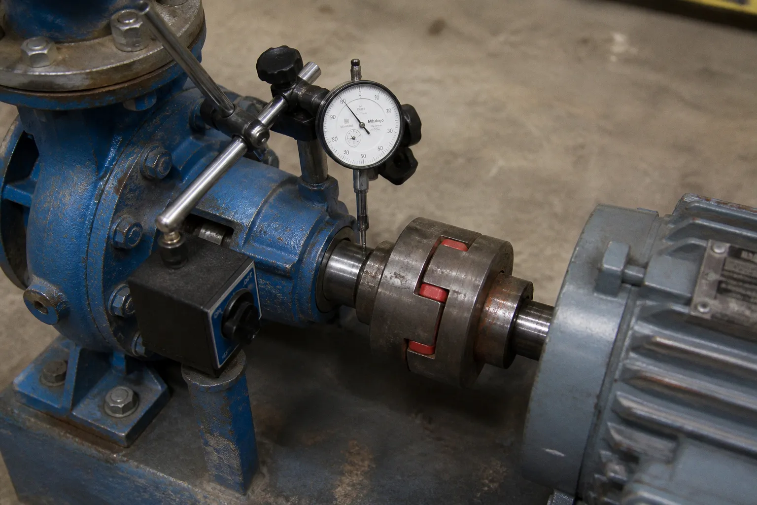
On the ground, the cause is often less dramatic than a cracked casing or a failed motor. The shafts are simply not aligned well enough for the operating conditions.
Compare car rental deals in United Kingdom
See available offersPartner link — DiscoverCars comparisonThat is where the choice between dial indicators and laser alignment systems becomes practical rather than theoretical. Both methods can produce precise shaft alignment when used correctly. The real difference lies in how much rotation, calculation, interpretation, and repeatable documentation the job demands—and in what your technicians can realistically do beside the pump during a production shift.
Alignment is not a paperwork exercise
When we talk about pump shaft alignment, we are talking about the relationship between the pump shaft and the driver shaft across the coupling. The goal is not to make two machine faces look visually parallel. The goal is to control angular and offset misalignment so that the coupling, bearings, seal, and shaft are not forced to compensate for installation error while the machine is running.
An uncorrected condition usually announces itself through several channels at once:
- vibration increases, sometimes most noticeably at coupling or bearing locations;
- bearings operate under additional load and may show premature wear;
- mechanical seals lose their operating stability and begin to leak;
- shafts can bend or experience repeated stress at the coupling;
- energy is wasted because the drive train is working against avoidable mechanical resistance.
The difficult part is that these symptoms do not always appear immediately after installation. A pump may run quietly during a short commissioning check and become troublesome only after thermal conditions change, the foundation settles, or the machine reaches its normal operating temperature. That is why the alignment method has to fit the equipment, the environment, and the way the service team actually works—not just the tool available in the workshop.
If you are comparing a dial indicator versus laser shaft alignment for pumps, start with the operating reality: how much shaft rotation can you obtain, how often do you align machines, how much calculation does the crew want to perform manually, and what evidence must be retained after the work is complete?
The best alignment method is not the one with the most impressive instrument; it is the one that produces a repeatable result under the conditions your crew faces on the floor.
How dial indicator alignment works
Dial indicators are a mature mechanical method, not a relic. The instrument itself dates back to 1883, when it was invented by a New England watchmaker, and the underlying principle remains useful because it is direct: a contact point moves against the shaft or coupling, and the technician observes the change as the shafts are rotated.
The two principal approaches are the rim-and-face method and the reverse-indicator, sometimes called cross-dial, method.
With the rim-and-face method, one indicator measures radial displacement at the rim of the coupling while another measures axial displacement across the face. The readings taken at different clock positions describe the offset and angular relationship between the shafts. The reverse-indicator method places indicators so that each shaft provides a reference for the other, allowing the technician to calculate the relative position across two measurement planes.
In practice, the familiar 9-12-3 position method is based on the geometry of readings taken at 90-degree intervals around the coupling. The technician records values at positions corresponding to 0, 90, and 180 degrees, then uses the change in readings to establish the correction. Depending on the selected technique and the available access, a complete reading commonly requires 180 to 360 degrees of shaft rotation.
That last requirement is where the method becomes demanding. If the pump and motor are coupled to a gearbox, piping, guard, or other equipment that restricts access, rotating the shafts through the required arc may be awkward. If the pump is stiff after an outage, or the coupling cannot be turned safely by hand, the technician is forced to solve a mechanical access problem before solving the alignment problem.
Dial indicators also introduce several points where technique affects the result:
- the brackets must be rigid and properly mounted;
- the technician must account for bracket sag;
- the shaft must be rotated in a controlled way rather than pushed through an inconsistent path;
- readings must be recorded and interpreted without mixing sign conventions;
- shim corrections must be calculated from the geometry of the machine;
- the final reading must be repeated after corrections and after tightening.
None of this makes dial indicators unreliable. A trained technician can achieve high accuracy with them. It does mean that the quality of the result depends heavily on the person performing the work, the condition of the brackets, and the discipline of the measurement process.
That dependence can be a strength in an experienced maintenance team. Mechanical indicators are comparatively simple, familiar, and less dependent on batteries, software, or a clean digital workflow. A crew that has aligned hundreds of pumps with reverse indicators may be faster and more confident with them than with a new laser system that has not yet become part of the daily routine.
What laser alignment changes
A laser system replaces the mechanical contact reading with a projected measurement between sensor units mounted on the shafts or coupling. The instrument measures how the shafts relate to each other as they are rotated, then uses the machine geometry to calculate the corrections required at the movable machine feet.
The most visible operational advantage is the reduced rotation requirement. Laser alignment systems can calculate shaft alignment with as little as a 40-degree rotation, while dial indicator procedures typically require at least 180 or 360 degrees for complete readings. When access is restricted, that difference is not a marketing detail. It may determine whether the alignment can be completed without removing additional hardware.
Laser tools also remove several manual steps from the workflow. They can compensate for bracket sag, calculate shim adjustments, account for thermal growth, and produce a digital compliance report, including a PDF record. This changes the task from a set of handwritten readings and calculations into a guided measurement-and-correction process.
For a technician standing beside a pump, the benefit is often less about the word “laser” and more about reduced cognitive load. The system can show whether the machine is high, low, left, or right, and it can update the correction after the operator enters or confirms the machine dimensions. That supports better tactile feedback during the physical part of the work: loosen the appropriate feet, add or remove shims, move the motor laterally, tighten, and measure again.
The distinction matters because operator fatigue is real. Alignment is often performed after a pump has been opened, cleaned, inspected, or reassembled, when the crew is already working in a confined area and under time pressure. Any method that reduces repeated calculations and unnecessary shaft rotation can make the job more manageable. It does not replace judgment, but it gives the technician more attention to spend on the parts that software cannot see: soft foot, pipe strain, damaged baseplates, loose hold-down bolts, or a coupling that is not seating correctly.
The comparison in working conditions
| Practical factor | Dial indicators | Laser alignment systems |
|---|---|---|
| Shaft rotation | Usually requires 180–360 degrees for complete readings | Can work with as little as 40 degrees, depending on the system and setup |
| Main calculations | Performed manually from indicator readings and machine geometry | Calculated by the instrument after dimensions and readings are entered |
| Bracket sag | Must be measured or compensated by the technician | Typically compensated automatically by the system |
| Shim correction | Calculated manually | Calculated and displayed by the instrument |
| Thermal growth | Requires separate calculation and application | Can be included in the alignment calculation |
| Documentation | Paper records or manually created reports | Digital records and PDF compliance reports can be generated |
| Environmental sensitivity | Mechanical readings are not affected by a laser beam path | Heat distortion, steam, and other conditions can disturb the measurement path |
| Dependence on operator skill | High, especially for setup and calculations | Still high for setup and machine diagnosis, but fewer calculations are manual |
| Investment | Relatively low equipment cost if indicators and brackets are already available | Equipment purchase can exceed $20,000; contractor alignment may cost roughly $800–$1,500 per job |
| Best fit | Skilled teams, routine machines, accessible couplings, low-complexity corrections | Frequent alignment work, restricted rotation, thermal compensation, repeatable reporting |
The table is useful only if we keep one qualification in view: neither system can compensate for a poor mechanical setup. A laser will calculate the wrong correction very efficiently if the dimensions are entered incorrectly, the brackets move, or the machine is not stable.
The hidden work before measurement
The instrument is only one part of precision shaft alignment. Before mounting either indicators or sensors, we need to establish whether the machine is ready to be measured.
Start with the base and hold-down condition. A pump and motor that shift while bolts are tightened cannot produce a stable final reading. Soft foot—the condition in which one or more machine feet do not sit firmly on the base—can make a correction appear to work in one state and disappear when the machine is secured. The same is true of a baseplate that is distorted or a hold-down bolt that is not clamping as intended.
Then consider the piping. Pipe strain can pull a pump casing away from its natural position when connected lines are tightened or when thermal loads develop. In that situation, the pump may be aligned perfectly while disconnected and misaligned as soon as the process piping is restored. A laser system does not make pipe strain disappear, and a dial indicator does not cause it; both methods simply reveal the machine relationship that exists at the time of measurement.
Coupling condition matters as well. Damaged elements, incorrect spacing, worn hubs, and dirt between mating surfaces can introduce errors that look like shaft misalignment. If the coupling is not seated properly, the alignment result will be built on a false reference.
A practical pre-measurement sequence is therefore:
1. Confirm that the pump and driver are installed in their normal mechanical condition, including the relevant piping and coupling arrangement.
2. Check that the base, feet, shims, and hold-down hardware are clean, stable, and capable of holding the correction.
3. Look for soft foot before spending time interpreting alignment readings.
4. Inspect the coupling and verify the correct separation and component condition.
5. Establish whether the shafts can be rotated safely and through the angle required by the chosen method.
6. Decide how thermal growth will affect the running position, especially if the pump and driver operate at significantly different temperatures.
7. Measure, correct, tighten, and measure again rather than treating the first acceptable reading as the finished job.
This is where an experienced technician remains essential. The laser can calculate a shim pack, but it cannot determine from a screen alone whether a pipe is pulling the casing, whether a foot is distorted, or whether a movement during tightening indicates a loose base.
When dial indicators remain the right choice
A dial indicator system is a sensible choice when the maintenance team already has strong mechanical alignment skills and the machines provide reasonable access. For a standard pump-and-motor train in a familiar layout, the method can be efficient, economical, and sufficiently precise.
It also works well when the alignment job is part of a broader mechanical inspection. An experienced technician may notice changes in coupling behavior, shaft condition, bracket stability, or machine movement that are easy to overlook when attention is concentrated on following a digital prompt. The instrument offers a direct relationship between what the contact point does and how the shaft moves.
Dial indicators can be especially appropriate when:
- the facility performs alignment infrequently but has trained mechanical personnel;
- the coupling can be rotated through the required range without excessive effort;
- the machine geometry is straightforward and well documented;
- there is no requirement for automatically generated digital reports;
- the environment is unsuitable for a laser beam because of steam, heat shimmer, or an obstructed measurement path;
- the team needs a robust method that does not depend on electronic charging or software.
The trade-off is that the method places more responsibility on the technician. Bracket sag, calculation errors, incomplete rotation, and inconsistent recording can all affect the outcome. A dial indicator is not difficult because it is old; it is demanding because it leaves more of the reasoning visible—and manual.
When laser alignment earns its place
Laser alignment becomes compelling when the plant has a recurring alignment workload, difficult access, multiple machine types, or a strong need to demonstrate what was done. The ability to measure with limited rotation is often the decisive factor on compact installations where guards, piping, or adjacent equipment make a full rotation impractical.
It is also valuable for teams managing a large maintenance program. A digital report can capture the initial condition, the correction, and the final result in a form that can be attached to a work order or equipment history. That creates continuity between shifts and between technicians. A future failure investigation has more to work with than a note saying that the motor was aligned.
The financial decision needs to be viewed in the same operational context. A laser alignment contractor may charge roughly $800–$1,500 for a job, while purchasing laser equipment can cost more than $20,000. Those figures are not a universal price list, and the actual cost varies by market, system, machine complexity, and service scope. They do clarify the basic choice: occasional alignment may favor contracting, while frequent alignment across critical assets may justify ownership.
If your team aligns a small number of accessible pumps, buying a high-end system may be difficult to justify. If alignment is part of planned maintenance across many pumps, motors, fans, compressors, and gearboxes, the value may come not only from the measurement itself but from shorter setup time, repeatable calculations, reduced operator fatigue, and better records.
Laser alignment does not remove the craft from the job. It moves the craft toward setup, diagnosis, and correction, where the consequences of a bad mechanical assumption are easier to see.
Thermal growth and the running machine
One of the most important differences between a cold alignment and a reliable operating alignment is thermal growth. The pump and driver may not occupy the same relative position at ambient temperature that they occupy after the equipment reaches process conditions. If the motor, pump, piping, or baseplate expands differently, the cold alignment may need an intentional offset so that the shafts become aligned while running.
Laser systems can include thermal growth compensation in their calculations. This is a meaningful advantage when the machine has known operating temperatures and the required values are available from the equipment manufacturer or a validated engineering assessment.
But the presence of a compensation field does not make the input correct. We still need trustworthy thermal data and a clear understanding of which machine is expected to move, in what direction, and by how much. A guessed value entered into a sophisticated tool remains a guessed value.
Dial indicator methods can accommodate thermal growth as well, but the technician must calculate and apply the correction separately. That may be entirely acceptable for a skilled team, particularly when the equipment history already contains established targets. The difference is workflow: laser systems bring the calculation into the measurement process, while dial indicators leave more of it to manual interpretation.
Environmental limits are part of the method
Laser tools are precise, but they are not immune to the factory around them. Extreme heat distortion can bend the apparent path of the beam, and steam in the measurement path can interfere with reliable readings. In a hot process area, the instrument may show a value that changes as the air above the machine shimmers or as a steam plume passes between the sensors.
This does not mean that laser alignment is unsuitable for industrial environments. It means the technician must recognize when the environment is compromising the measurement. Shielding the path, allowing conditions to stabilize, choosing an appropriate measurement window, or switching to a mechanical method may be the correct response.
Dial indicators have their own environmental concerns—corrosion, dirt, poor visibility, unstable mounting, and physical access—but they do not rely on a clear optical path. In a location where steam is persistent and the coupling is accessible, a dial indicator may provide the more dependable reading.
The right question is not whether one technology is universally more accurate. It is whether the measurement remains trustworthy in the conditions surrounding the pump at the time of the job.
What a useful alignment record should contain
A good alignment record should help the next person understand the machine, not merely prove that a tool was used. Whether the data comes from a paper worksheet or a digital PDF, the record should connect the readings to the physical equipment.
At a minimum, capture:
- the pump and driver identification;
- the coupling arrangement and relevant machine dimensions;
- the measurement method used;
- the initial alignment condition;
- soft-foot findings and corrections;
- shim changes and lateral movements;
- thermal growth targets, where applicable;
- final readings after tightening;
- any unresolved condition, such as pipe strain or restricted access;
- the technician, date, and operating context.
A digital report is useful because it can standardize this information and make it easier to retrieve. It is not useful if the report is saved without the machine identity, correction history, or explanation of abnormal conditions. Documentation should support future maintenance decisions, not become another file that nobody opens.
Choosing between the two methods
For most plants, the decision is not truly dial indicators versus laser systems as a permanent either-or choice. A mature maintenance program may use both. The selection can be made machine by machine.
Choose the method that best matches the following conditions:
- Accessible coupling and experienced alignment crew: dial indicators may be fast and economical.
- Restricted shaft rotation: laser alignment has a clear practical advantage because some systems can work with approximately 40 degrees of rotation.
- Frequent alignment across many assets: the reduced calculation burden and digital reporting of a laser system become more valuable.
- Steam, heat distortion, or an obstructed beam path: dial indicators may provide a more dependable measurement route.
- Known thermal growth targets: laser systems simplify the application of compensation, provided the input data is sound.
- Infrequent work and limited capital budget: a competent contractor may be more sensible than purchasing equipment costing more than $20,000.
- Strong internal mechanical expertise and no reporting requirement: indicators remain entirely capable of producing high-quality results.
- High operator fatigue or limited rotation access: reducing manual calculations and physical repositioning can improve both productivity and consistency.
Pump coupling alignment tolerance cannot be selected responsibly from a generic number copied from another machine. The acceptable condition depends on the coupling, speed, machine geometry, operating temperature, and applicable equipment requirements. A result that is acceptable for one pump train may not be appropriate for another. The method helps us measure and correct the relationship; it does not replace the need to understand the machine.
The practical conclusion
Dial indicator alignment and laser alignment are both precision shaft alignment techniques, but they place the work in different parts of the process. Indicators keep more of the measurement and calculation in the technician’s hands. Laser systems automate more of the geometry, reduce the required rotation, incorporate thermal growth compensation, and make documentation easier.
Neither method is foolproof. A laser can be disturbed by heat or steam, and it can produce a confidently calculated correction based on incorrect dimensions or an unstable machine. A dial indicator can achieve excellent accuracy, but only when the brackets are rigid, the readings are taken correctly, the shaft is rotated sufficiently, and the calculations are handled with care.
On the ground, the most valuable result is not a particular technology. It is a pump that runs with less vibration, protects its bearings and seal, wastes less energy, and does not demand another emergency intervention from the same tired crew. When the design of the alignment process gives technicians clearer feedback, fewer avoidable calculations, and a result they can document and trust, it improves more than the machine. It improves the working day of the people responsible for keeping that machine alive.