Pressure relief valve sizing errors: hidden capacity calculation traps
A relief valve can have the correct set pressure, the correct nominal inlet size, and a valid nameplate—and still fail the required duty. The failure is usually upstream of the valve selection.
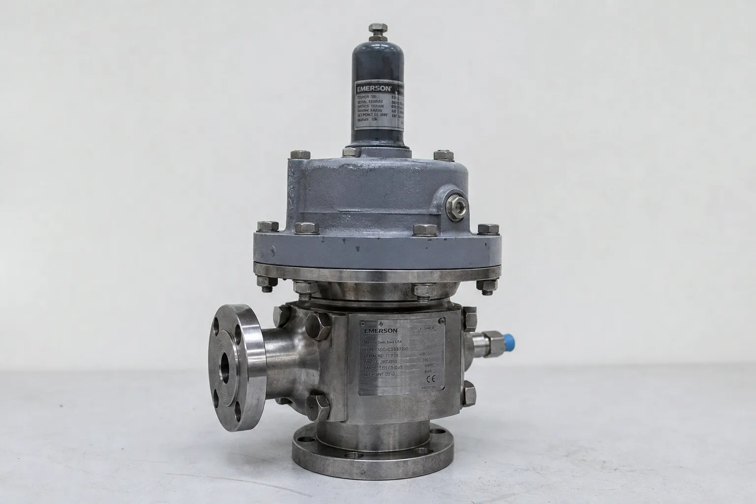
It begins in the pressure basis, the relieving scenario, or the piping model.
Pressure relief valve sizing calculation errors do not behave like minor tolerance drift. A gauge-to-absolute pressure mistake shifts gas or vapor capacity. An inlet line modeled at normal flow rather than rated relieving capacity can create instability. A discharge header treated as an afterthought can invalidate the selected backpressure correction. In flashing service, a familiar liquid equation can produce a number with no defensible physical basis.
The valve is not an isolated component. It is one constraint inside a pressure-relief system: protected equipment, inlet piping, valve mechanism, discharge line, header, and final disposal point. Capacity exists only when the whole path supports it.
1. Relieving pressure errors start with the wrong pressure basis
The most persistent safety valve set pressure mistakes occur before the area calculation starts. Engineers use the set pressure as though it were the relieving pressure. For compressible flow, that shortcut changes the calculation input that controls mass throughput.
For gas and vapor service, relieving pressure \(P1\) must be expressed as an absolute pressure. The working basis is:
- set pressure;
- plus permitted overpressure;
- plus atmospheric pressure;
- minus inlet-piping pressure loss.
The order matters. Set pressure is not relieving pressure. Gauge pressure is not absolute pressure. And inlet loss is not a mechanical-installation detail that can be excluded from the capacity model.
A valve set at 10 barg with permitted overpressure does not see 10 bar as the usable upstream condition during relief. It sees a higher vessel pressure at lift, reduced by the pressure loss between vessel and valve inlet. If the calculation uses gauge pressure where the equation requires absolute pressure, the error is structural. The calculated nozzle area may look precise to several decimal places. The result is still wrong.
This is especially damaging in low- and medium-pressure gas service. Atmospheric pressure is a larger fraction of the total absolute pressure there. The error rate increases because the spreadsheet often contains a mixture of barg, bara, psig, and psia inputs with no enforced unit logic.
A relief calculation is only as valid as its pressure reference. “Gauge” omitted from a cell label is not a documentation problem. It is a capacity problem.
The input sheet should make the pressure basis explicit. Not implied. A usable calculation record distinguishes at least these values:
| Pressure term | What it represents | Common failure mode |
|---|---|---|
| Set pressure | Valve opening setpoint | Used directly as relieving pressure |
| Overpressure | Permitted pressure rise above setpoint during the governing event | Assumed without matching the code path or scenario |
| Atmospheric pressure | Conversion term for absolute-pressure equations | Omitted in gas and vapor calculations |
| Inlet pressure loss | Loss from protected equipment to valve inlet at rated capacity | Calculated at normal flow, or ignored |
| Relieving pressure | Actual pressure available at the valve inlet during relief | Mixed between gauge and absolute units |
The same discipline applies to relief valve discharge coefficient errors. A discharge coefficient is not a generic performance multiplier that can compensate for incomplete process data. It belongs to the certified capacity basis and the selected method. Replacing certified factors with optimistic assumed values is not engineering simplification. It changes the capacity claim.
For a conventional or balanced spring-loaded valve, the valve’s certified behavior, the flowing medium, and the pressure conditions must remain aligned. A calculation that combines a vapor coefficient from one basis, a liquid density from another temperature, and a relieving pressure in gauge units has no coherent throughput model.
2. The inlet line controls stability, not only pressure drop
A relief valve does not receive vessel pressure directly. It receives the pressure remaining after the inlet line has consumed part of the available driving force. That distinction is responsible for a large share of overpressure protection sizing pitfalls.
API-based installation guidance commonly uses a maximum inlet pressure-loss target of 3% of valve set pressure. The number is often copied into a design note and then treated as closed. It is not closed until the loss is calculated at the valve’s rated relieving capacity and with the actual inlet geometry.
The relevant hydraulic system includes:
- inlet pipe internal diameter, not nominal pipe size;
- actual straight-run length;
- elbows, tees, reducers, strainers, and isolation-valve geometry where applicable;
- inlet branch orientation;
- fluid density and phase condition at relieving conditions;
- rated valve flow, not expected operating flow.
A line that looks adequate at process throughput can be unacceptable at emergency throughput. The relationship is nonlinear. As flow increases, frictional loss and local losses rise sharply. A short inlet line with an undersized bore or a restrictive fitting can consume the margin quickly.
Poorly evaluated arrangements can produce inlet losses of 10%, 20%, or 30% of set pressure. At that point, the concern is no longer only reduced flow. In direct-acting pressure relief valves, inlet losses above valve blowdown can cause chatter or rapid cycling.
Chatter is a system response. The valve opens, flow accelerates through the inlet, pressure at the valve inlet collapses, the valve closes or loses lift, pressure recovers, and the cycle repeats. The result is unstable throughput, seat damage, vibration, and a relief device that no longer behaves like the capacity curve assumed in the calculation.
This is why “the valve is mounted close to the vessel” is not sufficient design evidence. Distance is one variable. Restriction count and geometry often dominate.
Model the inlet at the capacity you are claiming
The practical sequence is direct:
1. Establish the governing relieving load and the initial required capacity.
2. Select a preliminary valve and certified orifice capacity basis.
3. Calculate inlet loss at the preliminary valve’s rated relieving flow.
4. Compare the loss against the applicable installation target and the valve’s stability constraints.
5. Revise the inlet configuration or valve selection if the hydraulic result is not acceptable.
6. Repeat after any change in valve capacity, line size, or scenario.
This creates a feedback loop. That is expected. One-pass sizing is attractive because it reduces latency in a project schedule. It also raises the error rate when piping and valve selection are interdependent.
A larger valve can increase rated flow. It can also increase inlet-line loss if the inlet piping remains unchanged. The larger nominal valve is not automatically the lower-risk answer.
3. Backpressure is a network calculation
Backpressure mistakes emerge when the discharge line is treated as downstream plumbing. It is part of the valve operating envelope.
Two backpressure categories need separate treatment:
- Superimposed backpressure exists at the valve outlet before the valve opens. It may come from a common header, another operating relief device, a flare system, or a pressurized collection system.
- Built-up backpressure develops after the valve opens because flow through the discharge piping and header creates pressure drop.
These pressures do not have identical effects on every valve design. Conventional spring-loaded valves, balanced bellows valves, and pilot-operated relief valves have different tolerance limits and correction logic. The selected valve type is therefore a system decision, not a catalog filter.
API 520 Part I requires that superimposed backpressure from another relieving or venting source does not prevent valve opening. Built-up backpressure in the discharge line and common header must also remain within the selected valve’s allowable limits.
That sentence has a simple operational implication: calculate the whole discharge network for simultaneous credible relief cases.
A common model failure is to size each valve independently, then connect all outlets to a common header later. The individual calculations may be internally correct. The combined network is not. When multiple valves discharge, the header pressure rises. That added pressure changes valve capacity and may alter whether another valve can open as intended.
For balanced pressure relief valves, the calculation is iterative. The preliminary valve area is selected using a backpressure correction factor, often represented as \(Kb\). Then the discharge line and header losses are calculated. The resulting backpressure is checked. The factor, effective capacity, and valve size are recalculated. The loop continues until the valve, discharge system, and allowable limits converge.
| Valve and flow condition | Backpressure handling | Incorrect shortcut |
|---|---|---|
| Conventional spring-loaded PRV | Capacity and operation can be strongly constrained by outlet pressure | Assuming a common header has no effect because the valve is “pressure rated” |
| Balanced PRV | Requires backpressure evaluation and iterative correction where applicable | Applying one preliminary \(Kb\) factor and stopping |
| Pilot-operated PRV in critical-flow compressible service | API guidance permits \(Kb = 1.0\) under this specific condition | Using \(Kb = 1.0\) for liquid service, subcritical flow, or any pilot valve |
| Any valve on a shared discharge system | Requires credible simultaneous-flow and header hydraulic analysis | Calculating branch lines only |
The \(Kb = 1.0\) condition is regularly overextended. It applies to pilot-operated PRVs in critical-flow compressible service. It is not a general exemption from discharge-system analysis. It does not remove the need to establish the flow regime, confirm the pilot valve configuration, or model the header.
Backpressure is not an outlet-side correction factor. It is a system variable that can change opening behavior, lift, and delivered capacity.
The discharge line must also be reviewed for mechanical consequences: reaction forces, thermal effects, drainage, condensate accumulation, and the destination’s pressure limits. A hydraulically acceptable header that traps liquid in a vapor-relief path still has a configuration defect.
4. Flashing and two-phase relief are not diluted single-phase cases
The largest calculation risk appears when a liquid-relief method is applied to flashing service because the fluid entered the valve as liquid.
That is not the relevant condition. The relevant condition is the phase behavior during pressure reduction through the valve and discharge system.
A liquid can flash as pressure falls across the relief valve. A two-phase mixture can form upstream, within the nozzle, or in the discharge line. Density changes, slip behavior, choking conditions, and vapor generation then alter the capacity model. The throughput cannot be inferred reliably from a standard incompressible liquid equation or an ordinary vapor equation.
There is no single universally accepted method that handles every two-phase application. There is also no universally recognized certification procedure for PRV capacity across all two-phase flow conditions. This is not a gap that a spreadsheet template resolves.
The reduced Omega method described in API-based practice is one structured approach, but it requires property data at two defined states:
- at the PRV inlet;
- at 90% of the absolute flowing pressure.
For a flashing liquid, the second state may correspond to saturation pressure at relieving temperature. These are not values that should be estimated from a process datasheet with a single normal-operating density. They typically require a property database or a process-simulation flash calculation.
The required inputs may include composition, temperature, pressure, vapor fraction, molecular weight, heat-capacity ratio, density, viscosity, and phase-equilibrium data. If the system contains a multicomponent hydrocarbon mixture, reactive fluid, dissolved gas, or unstable condensate, the cognitive load rises further. The model must track the actual relieved state, not the normal process description.
Signals that the single-phase model has expired
A separate two-phase review is required when the relieving path includes conditions such as:
- liquid pressure falling below vapor pressure at the prevailing temperature;
- depressuring of a vessel containing volatile liquid;
- heat input that generates vapor during relief;
- loss of cooling that moves the inventory toward boiling;
- liquid containing dissolved gases that evolve during pressure reduction;
- a control or check-valve failure that changes both pressure and phase regime;
- a discharge system that imposes pressure changes large enough to alter flashing behavior.
The error is often procedural. The scenario owner supplies a liquid flow rate. The valve specialist sizes for liquid. The piping group later identifies flashing in the discharge line. Each discipline has completed a local task. The system has no consistent state model.
The correction is not to add a conservative multiplier without defining its basis. The correction is to return to the governing scenario and establish fluid properties through the valve and discharge path. In difficult service, this can require specialist process modeling, vendor review, and a documented decision on the selected methodology.
5. The governing scenario sets the required relief load
A relief valve cannot be sized from a nominal line flow or vessel volume alone. The required relieving load comes from the controlling overpressure scenario.
Common initiating events include utility or power failure, external fire, cooling-water loss, automatic-control failure, blocked outlet, thermal expansion of blocked-in liquid, and check-valve malfunction. These are not interchangeable cases. Each can produce a different fluid state, relieving pressure, duration, and required capacity.
The controlling scenario is not always the most dramatic one. External fire may govern vapor generation for one vessel. A failed control valve may govern gas inflow for another. Cooling loss may create the highest pressure accumulation in a heat exchanger system. A check-valve malfunction can connect high-pressure inventory to lower-rated equipment and generate a load that the normal-process model never considered.
The analysis record should identify, for each credible scenario:
1. The initiating event and failed safeguards assumed unavailable.
2. The protected equipment and its pressure limit.
3. The permitted accumulation or overpressure basis under the applicable code path.
4. The relieved fluid state at the valve inlet.
5. The required relieving rate.
6. The inlet pressure loss at rated capacity.
7. The discharge-system backpressure under credible simultaneous relief.
8. The selected valve’s certified capacity and applicable correction factors.
9. The final disposal path and its constraints.
This is the minimum traceability needed to review the design. It also reduces rework. Without it, process, mechanical, piping, and vendor calculations operate with different assumptions and high handoff latency.
Certification data must remain separate from calculated demand. A manufacturer’s rated relieving capacity is based on defined test and certification conditions. For pressure vessels within the cited U.S. Coast Guard regulatory scope, certification references flow testing at 110% of set pressure for valves rated under ASME Section VIII UG-131; steam certification uses a different 103% condition. These figures are not universal defaults for every jurisdiction, vessel type, or code route.
The applicable regulatory and contractual basis must be identified before the final valve selection. API 520 Part I, 10th edition, and API 520 Part II, 7th edition, are listed with publication dates of October 28, 2020. API 521, 7th edition, is listed as published June 2, 2020. These documents provide a current technical baseline for refinery pressure-relief practice, but they do not eliminate project-specific code requirements.
Nominal port size is not a capacity certificate. Neither is a familiar orifice designation. The selected device must deliver certified capacity under the actual relieving conditions after the inlet and discharge system have been accounted for.
The usable design rule: validate the path, not the valve
Most pressure relief valve sizing calculation errors are interface errors. Process data is separated from valve selection. Valve selection is separated from inlet hydraulics. Inlet hydraulics is separated from the discharge header. The calculation appears complete because every team has produced a document.
The protected system does not operate in documents. It operates as one flow path.
Use these design heuristics to reduce error rate:
- Define the governing relieving scenario before selecting a valve orifice.
- Use absolute relieving pressure for gas and vapor sizing. Label units at every calculation boundary.
- Calculate inlet pressure loss at rated relieving capacity, not normal operating throughput.
- Treat a 3% inlet-loss target as a hydraulic result to demonstrate, not a value to copy into a specification.
- Model superimposed and built-up backpressure across the full discharge network, including credible simultaneous releases.
- Iterate balanced-valve sizing until valve area, \(Kb\), discharge losses, and allowable backpressure converge.
- Apply \(Kb = 1.0\) only where the specific pilot-operated, critical-flow, compressible-service condition is established.
- Escalate flashing and two-phase service to a property-based method. Do not force it into a single-phase equation.
- Keep certified valve capacity distinct from calculated system demand.
- Preserve the scenario, fluid-property, piping, and certification assumptions in one reviewable calculation package.
A relief valve is a final barrier. Its design margin is not created by selecting a larger catalog item. It is created by reducing uncertainty across the pressure basis, flow regime, inlet path, discharge network, and governing scenario.