Centrifugal pump impeller trimming methods for lower power consumption
Walk up to a centrifugal pump on the plant floor and listen for a moment. If the discharge handwheel is wound nearly shut and a hot bypass loop is dumping flow back to the suction tank, the pump is…
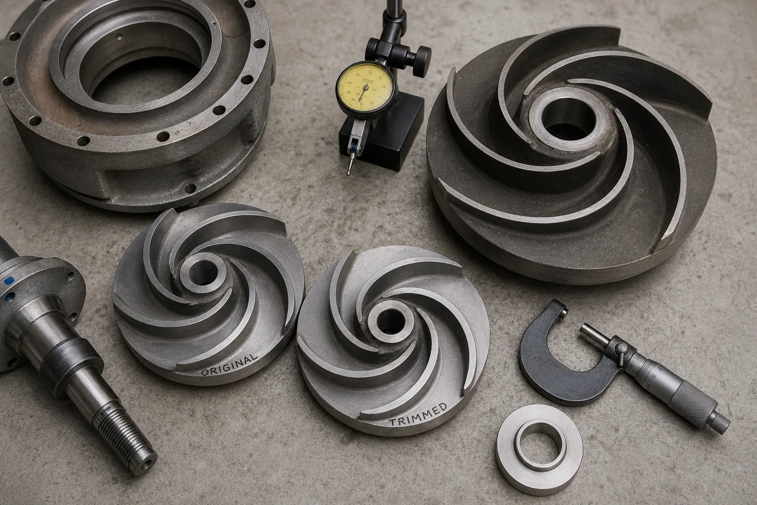
Walk up to a centrifugal pump on the plant floor and listen for a moment. If the discharge handwheel is wound nearly shut and a hot bypass loop is dumping flow back to the suction tank, the pump is telling you, in the language of gauges and skin temperature, that it is bigger than the job you are asking it to do. We have all stood in front of that installation at some point: an operator with a gloved hand resting on the throttling valve, watching the manometer hold a number the system does not actually need, while the motor hums along at full nameplate speed and the kilowatt-hour meter keeps spinning the wrong direction. That friction point — oversized pump, throttled system, wasted input power — is precisely where impeller trimming earns its keep.
Impeller trimming is the practice of machining the outside diameter of a centrifugal impeller to permanently reduce the energy it adds to the fluid. It is not a control method, it is not reversible, and it is not a substitute for variable-speed drives when the duty point swings around. What it is, in the daily realities we work with on the floor, is a one-time correction for a stable duty that has been misjudged on the conservative side — or that has shifted since the original hydraulic selection. Done with the manufacturer's published performance curve in front of you, and with the operator's actual hand on the bypass valve as the reference point, trimming is one of the cleanest energy-saving moves available to us on a fixed-speed pump.
When the Pump Is Bigger Than the Job
A pump that has been conservatively selected, or that now serves a process whose demand has fallen, shows up on shift in very recognizable ways. The control valve sits below 30% open at the design flow. The bypass line runs warm. The motor current is far below nameplate, but the kilowatt-hour meter still records the draw that a fully loaded pump would have used if the throttling had not been doing the work of energy recovery. The cost we feel on the floor is not just a line item on the utility bill — it is the operator's time spent re-checking a valve that has no business being there, and the maintenance hours tied to a mechanical seal that sees more thermal cycling than it was rated for.
If you are facing this situation, then trimming the impeller is one of the corrective paths worth taking seriously, alongside a variable-frequency drive or a hydraulic re-selection. The choice between them comes down to one question: is the duty point going to move around after the correction, or is it stable? If the process flow and head are steady for the foreseeable life of the pump, a properly trimmed impeller gives you a permanent right-sizing at a fraction of the cost of a new impeller or a new drive. If the duty point swings with batch changeovers, seasonal load shifts, or multiple parallel pump configurations, trimming is the wrong tool — and we will come back to that in a moment.
Impeller trimming is a permanent right-sizing for a stable duty, not a knob you can turn when the process changes its mind.
Reading the Affinity Rules the Way We Read a Recipe
When we trim a diameter, the first thing we want to know is what the pump will do afterward at the same rotational speed. The affinity laws give us a working estimate, the same way a recipe gives you the proportions for a different pan size before you actually bake. For a small change in diameter at constant speed, the standard relationships are:
| Quantity | Approximate ratio at constant speed |
|---|---|
| Flow (Q) | Q₂ / Q₁ ≈ D₂ / D₁ |
| Head (H) | H₂ / H₁ ≈ (D₂ / D₁)² |
| Brake horsepower (P) | P₂ / P₁ ≈ (D₂ / D₁)³ |
So a 2% reduction in impeller diameter moves flow down by roughly 2%, head down by roughly 4%, and required input power down by roughly 8%. A 5% reduction gives about 5% less flow, roughly 10% less head, and somewhere in the neighborhood of 14–15% less input power. The DOE sourcebook uses that small-change example for a reason: these relationships hold best when the diameter change is small relative to the original, and when the system curve does not introduce its own surprises.
We use the cube relationship on power carefully. The (D₂/D₁)³ factor is an estimate of the brake horsepower at the new duty point. What you actually save on the electricity bill depends on where the new operating point lands on the system curve, the motor's efficiency at the reduced load, the hours the pump runs, and the rate you pay per kilowatt-hour. The affinity rule is the recipe; the utility savings are the dish that comes out of the oven, and they will not match the recipe until you check both curves against each other. The Hydraulic Institute guidance reinforces this point directly: affinity rules are reasonable for about a 5% impeller-diameter reduction, and beyond that the OEM's published performance curve for the specific pump model is the source you trust.
Why Trimming Lowers Hydraulic Efficiency
Here is the trade-off that surprises people on the floor. Trimming the impeller reduces the input power the pump draws from the motor, but it also reduces the pump's own hydraulic efficiency. The reason is mechanical, and it lives inside the volute. As the outside diameter of the impeller shrinks, the clearance between the impeller tip and the casing cutwater grows. That gap is where internal recirculation lives — fluid that escapes back from the discharge side of the impeller to the suction side without doing useful work. A larger tip-to-cutwater gap means more of that recirculation, more head lost to it, and a pump that, on its own merit, is a little less efficient than it was before the cut.
The savings we are after are system-level savings: less power drawn to move the same flow through an unthrottened system, even when the trimmed pump itself is fractionally less efficient per gallon.
This is the friction point worth understanding before you cut metal. The comparison we want to make is not "the trimmed pump versus the untrimmed pump on a test stand." It is "the trimmed pump running unthrottled at the real duty versus the untrimmed pump pushing the same flow past a half-closed valve and a hot bypass." In that comparison, trimming almost always wins — but only when the duty point is stable, and only when we have actually re-mapped the operating point on the system curve rather than trusting the affinity-law arithmetic on its own.
How Far the Diameter Can Actually Go
Now we get to the question every machinist asks us on the floor: how small can you go? The honest answer is: do not let the affinity laws decide. Let the manufacturer's published minimum impeller diameter decide.
As a working envelope, the engineering guidance most of us reach for first is this: most centrifugal pumps should not be trimmed below roughly 75% of their maximum published impeller diameter, and diameters are rarely reduced below 70% of the original size because performance prediction and efficiency become unreliable below that line. Those two numbers are the rule of thumb we keep in our head; the rule we actually work to is the minimum diameter on the OEM's published performance curve for the specific pump model and specific impeller pattern. If the curve stops at 220 mm, you do not cut to 200 mm on the strength of a 70% rule, even if the math says it would be safe. You call the manufacturer, or you read the curve again, or you consider a different remedy.
Trimming suitability also depends on the impeller geometry, and this is where the conversation often goes sideways if we treat all impellers as the same part. The Hydraulic Institute is clear on this:
| Impeller type | Trimming response |
|---|---|
| Radial (Francis-type) centrifugal | Trims well; the most common and predictable case |
| Mixed-flow | Tolerates less diameter reduction than radial |
| Axial-flow (propeller) | Rarely trimmed; geometry is dominated by blade angle, not diameter |
| Multistage centrifugal | For major corrections, removing a stage is often preferable to trimming |
If you are standing in front of a mixed-flow pump and a colleague suggests a generous trim, that is the moment to pause and check the OEM data carefully rather than reaching for the calipers.
Cavitation Margins and the Suction Side
After the cut, before the pump goes back on line, we have to do one job that is easy to skip on a busy shift: re-verify the net positive suction head required, NPSHR, against the suction-side conditions we actually have at the new duty point. The reason this matters is that trimming can increase NPSHR in some pumps, because the head characteristics and the eye geometry interact differently at the smaller diameter. If the available NPSH at the suction — NPSHA — does not stay comfortably above the new NPSHR across the full operating range, cavitation moves from a theoretical risk to a daily one.
On the factory floor this looks like a few familiar signs: noise that an experienced operator can hear before an instrument can measure it, vibration that does not match the mechanical balance, and pitting on the impeller suction surface when the pump comes out for inspection. For services that handle aggressive, hot, or near-saturated liquids — chemical duty, hot water, light hydrocarbons — the margin between NPSHA and NPSHR is the kind of thing we protect deliberately, because the consequence of getting it wrong is not just a damaged impeller but a process incident and a long, expensive cleanup.
So before you commit to a diameter, pull the manufacturer's NPSHR curve for the trimmed impeller over the expected flow range, compare it to the NPSHA you actually have at site conditions, and keep a margin that respects the service. If the margin is thin, the right move is to leave the impeller a little larger, or to address the suction side, not to push the trim and hope for the best.
Bringing the Lathe to the Pump, Not the Pump to the Lathe
On the practical side, machining an impeller is a job that rewards preparation. The manufacturer publishes the trim diameters that are supported by performance data, and on some models — for example the stainless-steel patterns covered by the Xylem Bell & Gossett trimming manual — the manufacturer specifies whether the reduced diameter requires an "Angle Cut" on the outer edge rather than a flat face. That detail is not cosmetic; it affects how the impeller exits the volute and how the head curve behaves at the new operating point.
A few working points we walk through with the shop before any cut:
- Confirm the target diameter against the OEM's published performance curve and minimum-diameter limit, not against an affinity-law extrapolation.
- Confirm the cut geometry — flat face versus angle cut — from the model-specific manual, and mark it on the workpiece so the machinist sees it on the first pass.
- Verify the lathe, tooling, and spindle parameters are appropriate for the impeller material; for the stainless patterns in the Xylem manual, the recommended lathe capacity is on the order of 30 hp (22 kW) or greater, with surface-speed guidance in the neighborhood of 460 SFM (about 76 m/min) on the tooling example given.
- After machining, balance the impeller to the grade specified by the manufacturer; do not assume the original balance carries through after material has been removed, especially if the cut is not perfectly symmetrical across all blades.
- Inspect the suction-eye and back-side surfaces for any damage introduced by the cut or by handling, and verify the mechanical seal faces and O-ring surfaces are clean and undamaged before reassembly.
That last point — putting the pump back together carefully — is the moment the operator feels the difference. A trimmed impeller, properly balanced, with a fresh mechanical seal set and the throttling valve now sitting in a sensible mid-stroke position, changes the texture of the shift.
What Trimming Is Not For
Before we close, it is worth saying out loud what trimming is not, because on the floor the boundaries matter as much as the practice.
Trimming is not a reversible control method. Once the diameter is cut, it is cut. If the duty point is going to swing — different flows on different days, seasonal demand, batch changeovers — the right tool is a variable-frequency drive, or parallel pump staging, or both. Trimming a pump that needs to operate over a range is how you end up with a pump that is right for one day and wrong for the next, and that is a different kind of waste entirely.
Trimming is also not a substitute for fixing a mis-selected pump that is fundamentally the wrong hydraulic family for the service. If the original selection put a radial-flow pump into a head-and-flow regime that truly calls for a mixed-flow or axial-flow geometry, no amount of diameter reduction will get you there cleanly. In that situation the conversation we owe the operator is a longer one about hydraulic re-selection, not a shorter one about the lathe.
The Shape of the Shift After the Cut
When the impeller is trimmed correctly, the pump fits its duty, the operator's hands stop fighting a throttling valve, and the bypass loop goes cold. That is the design outcome we are after: a piece of equipment that matches the real daily work of the people who run it, instead of one that has to be coerced into its job with a half-closed valve and a warmed-over bypass. The kilowatt-hour savings are real, and they will show up on the next utility bill. The change that matters more, the one an operator will mention to the next shift without being asked, is that the pump now feels like it belongs in the system it is serving. That, more than any cube-law estimate, is how we know the trim was the right call.