Diaphragm pump pulsation dampeners: sizing formulas and pressure limits
A diaphragm pump does not produce “steady flow” because a brochure says it does. It produces pulses.
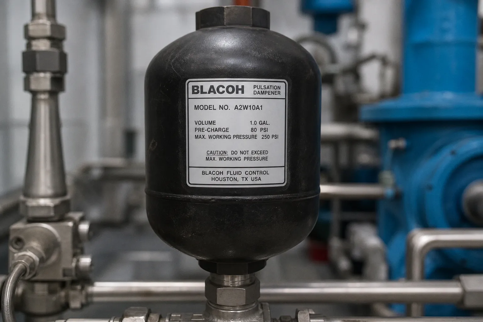
The pipe, valves, flowmeter, hose, skid frame, and downstream process all get to experience those pulses in their own unpleasant way: pressure spikes, noisy instruments, check valves chattering, erratic dosing, and fittings that somehow become everyone’s surprise maintenance project.
A pulsation dampener can clean this up. It can also become expensive stainless bloat bolted to a line because someone sized it from nominal flow alone. I see that mistake constantly. Flow rate is only one input. For a defensible diaphragm pump pulsation dampener sizing calculation, you need the volume displaced per stroke, pump configuration, mean pressure, permitted pressure variation, and the gas inside the dampener. Skip any of those, and the result is not engineering. It is optimism with fittings.
A dampener is not a generic accumulator. It has to match the pulse source, the pressure envelope, and the way the pump actually cycles.
Start with the sizing equation, not the catalog diameter
For metering-type diaphragm, piston, and plunger pumps, a published sizing method defines required nominal dampener capacity as:
C = [V × K × (P / Pmin)^n] / [1 − (P / Pmax)^n]
Where:
- C is the required dampener capacity.
- V is the pump volume per stroke.
- K is the factor for the pump’s piston/plunger arrangement and action.
- P is mean operating pressure.
- Pmin is the lowest acceptable pressure during a cycle.
- Pmax is the highest acceptable pressure during a cycle.
- n is the gas exponent: it changes with nitrogen or compressed air.
The formula looks more elaborate than it is. Its purpose is brutally practical: determine how much compressible gas volume the dampener needs to absorb part of the liquid slug and release it between pump strokes without allowing pressure to wander beyond the process tolerance.
The industry habit I distrust is this: “The pump is rated at X flow, so select the dampener listed for X flow.” That logic ignores the waveform. A small simplex metering pump can generate a much harsher pulse pattern than a larger multi-cylinder unit. The nominal hourly flow may look tame; the displacement event is not.
The dampener responds to each displacement event, not to an annualized flow number on a purchase order.
For a first-pass calculation, the commonly used allowable fluctuation is ±5% of mean pressure. With mean pressure P and allowable fractional variation D, the limits are:
- Pmin = P − (P × D)
- Pmax = P + (P × D)
If the target is ±5%, then D = 0.05. A process operating at a mean pressure of 100 units in the chosen pressure convention would therefore use Pmin of 95 and Pmax of 105.
That tolerance is not holy scripture. A chemical injection point, analytical instrument loop, spray process, or fragile membrane system may demand tighter control. A rugged transfer circuit may tolerate more movement. The tighter the allowed pressure band, the more capacity the dampener must provide. Physics remains irritatingly resistant to cost-cutting.
Find stroke volume before you touch a K-factor
The flow figure on a pump datasheet is usually expressed as a rate: gallons per hour, litres per hour, gallons per minute. The equation needs volume per stroke.
For a pump with known flow rate and stroke rate, calculate it this way:
1. Convert the rated or actual flow to gallons per minute.
2. Divide that value by strokes per minute.
3. The result is gallons per stroke.
4. Multiply by 231 to convert US gallons to cubic inches.
In shorthand:
V = (gallons per minute ÷ strokes per minute) × 231
Use the pump’s real operating point where possible. I would not size a dampener from a nameplate flow rate if the pump spends most of its life at reduced stroke length, variable frequency, or a different backpressure than the catalog test condition. That is how systems acquire unnecessary volume, sluggish response, and a nice big invoice.
A simple stroke-volume example
Assume a metering diaphragm pump delivers 30 gallons per hour at 60 strokes per minute.
First, convert the flow:
- 30 gallons per hour ÷ 60 = 0.5 gallons per minute
Then calculate displacement per stroke:
- 0.5 ÷ 60 = 0.00833 gallons per stroke
- 0.00833 × 231 = approximately 1.93 cubic inches per stroke
That 1.93 cubic inches is the starting point for the dampener calculation. It is not the final dampener size. It is the liquid slug that the dampener must help manage.
A few traps show up here repeatedly:
- Rated flow is not always actual flow. Slip, suction conditions, viscosity, stroke adjustment, and bypass arrangements can alter delivered volume.
- Stroke rate matters. Two pumps with identical hourly flow can have completely different per-stroke displacement.
- Variable-speed systems need an operating envelope. If frequency changes, the pulse rate changes; if stroke length or delivered volume changes too, the sizing basis moves with it.
- Units quietly destroy calculations. Mixing gauge pressure, absolute pressure, bar, psi, litres, and cubic inches without a deliberate conversion step is not a minor clerical error. It is a design defect.
For an AODD pump, this gets less tidy. The cycling pattern depends on air supply, fluid resistance, suction conditions, valve behavior, and the pump’s own air valve. There is no single universal formula that I would trust across every air-operated double-diaphragm design merely because the word “diaphragm” appears on the box.
K-factors: where pump configuration stops being a footnote
The K-factor accounts for how the pump configuration shapes pulsation. More pumping elements and more evenly distributed discharge events generally reduce the severity of each individual pulse. This is not mysterious. It is just why a triplex arrangement behaves differently from a simplex machine.
Published factors for metering-style pumps are as follows:
| Pump configuration | Single-acting K-factor | Double-acting K-factor |
|---|---|---|
| Simplex | 0.60 | 0.25 |
| Duplex | 0.25 | 0.15 |
| Triplex | 0.13 | 0.06 |
| Quadruplex | 0.10 | 0.06 |
The contrast is worth staring at. A simplex, single-acting pump uses 0.60. A triplex, single-acting pump uses 0.13. Calling both of them “diaphragm pumps” and assigning the same dampener volume is taxonomy failure dressed as simplification.
A single pumping chamber produces a different problem from three phased chambers. Treating them as equivalent creates predictable over-sizing or under-sizing.
For the 1.93 cubic-inch-per-stroke example above, a simplex single-acting pump has a much larger K contribution than a duplex or triplex design. If someone selects a compact dampener using a triplex assumption for a simplex pump, the installation will not become more sophisticated. It will simply underperform.
Conversely, blindly carrying the simplex factor into a multi-head pump specification can create unnecessary vessel volume and cost. More capacity is not always safer. Oversized dampeners can complicate response, package dimensions, support loads, and maintenance without curing the real issue, which may be poor piping or a badly selected pressure-control valve.
Nitrogen and compressed air do not calculate the same way
The gas charge is not a detail to fill in after procurement. It is part of the math.
In the sizing equation, the gas exponent n changes by charging medium:
| Charging gas | Exponent n |
|---|---|
| Nitrogen | 0.714 |
| Compressed air | 1.0 |
That difference materially changes calculated capacity. So no, a design team cannot calculate a nominal volume with one gas and casually charge the field unit with another because that is what happened to be connected to the utility header.
Nitrogen generally gives a cleaner, more stable answer for many industrial dampener applications because it is dry and inert. But the correct choice still depends on the system, fluid compatibility, maintenance practice, site rules, and the exact dampener design. A compressed-air charge may be appropriate in an installation designed around controlled air supply. A sealed nitrogen pre-charge may make more sense where a stable charge is the goal.
What I will not endorse is vague language such as “charge it to operating pressure.” Which operating pressure? Mean discharge pressure? Maximum pump pressure? A fluctuating value at a remote gauge? The instruction means nothing until the pressure basis and control method are defined.
For discharge-side dampeners, one manufacturer gives approximately 80% of expected mean system pressure as a general starting point for pre-charge. That is useful commissioning guidance, not a universal setting. The charge may need adjustment after startup because real piping systems contain all the things preliminary calculations politely ignore: long branches, dead legs, restrictive fittings, valves with questionable behavior, and process changes nobody included in the original pump schedule.
“Set it and forget it” is not commissioning. It is how a dampener becomes another unexplained object in the line list.
AODD dampeners are not just metering dampeners with a different label
Air-operated double-diaphragm pumps need their own branch in the decision tree. Their discharge pressure can vary significantly with air supply and downstream resistance. Their cycling behavior is less uniform than a controlled metering pump. And the dampener may use an adjustable or automatic air-control arrangement rather than a fixed gas pre-charge.
That distinction matters.
Some dampeners for AODD service use continuously supplied and regulated air to track liquid discharge conditions. In one manufacturer’s guidance for an air-operated pulsation dampener, the dampener air supply should sit at least 10 psig (0.7 bar) above mean liquid discharge pressure at the pump outlet. For pump ratios above 1:1, the dampener air pressure must also follow the pump ratio so the system does not overpressurize.
This is not interchangeable with the approximate 80% fixed-pre-charge starting point used for certain discharge-side dampeners. They are different control concepts for different equipment designs.
Here is the distinction without the usual catalog noise:
| Application condition | Practical dampener approach |
|---|---|
| Metering diaphragm pump with stable operating pressure | Calculate nominal capacity from stroke volume, K-factor, pressure band, and selected gas exponent; establish the specified pre-charge method. |
| AODD pump with changing discharge pressure | Evaluate an adjustable or automatic air-controlled dampener designed to follow operating pressure. |
| Transfer line with pressure spikes near the pump outlet | Put the dampener close to the discharge source, then verify the exact model’s pressure and material limits. |
| Suction-side instability, inlet starvation, or liquid-column separation risk | Assess an inlet stabilizer or suction-side dampener rather than pretending a discharge unit can solve every upstream problem. |
A manufacturer may claim a listed AODD dampener range can achieve flow up to 92% pulsation-free under stated conditions. Fine. That is a model-specific performance statement, not a promise that every AODD installation will suddenly behave like a centrifugal pump. Fluid viscosity, solids, line length, pipe flexibility, pump speed, and actual pressure range all get a vote.
Pressure limits are a model property, not a category property
“Diaphragm pump pulsation dampeners are rated to 125 psi” is the sort of statement that survives only because nobody asked the next question: which dampener, in which material, at which temperature?
Pressure limits vary by manufacturer, construction, elastomer selection, temperature, connection method, and pressure-control arrangement. Even within one product family, the difference can be immediate. In Graco i100 examples, an aluminum-cover model has a maximum fluid working pressure of 125 psig (8.6 bar), while a polypropylene-cover model is limited to 100 psig (6.9 bar).
Same broad product category. Different materials. Different limits. That is not bureaucracy. That is the design boundary.
When reviewing a proposed dampener, I would map these values against the actual system:
- Maximum pump discharge pressure, not merely normal operating pressure.
- Air pressure range and pump ratio for air-operated systems.
- Dampener fluid-side working-pressure rating.
- Gas-side or air-control rating where applicable.
- Temperature derating for the vessel, diaphragm, seals, and housing.
- Chemical compatibility with the pumped fluid and any cleaning medium.
- Relief-valve setting and the location of isolation valves.
- Whether the pressure rating applies to a pulsating service condition, not just a static vessel test.
Do not let a materials substitution slip through as a procurement “equivalent.” Polypropylene, aluminum, stainless steel, PVDF, and lined construction do not just alter corrosion resistance and price. They can alter pressure capability, temperature range, weight, mechanical robustness, and the consequences of a failure.
The pressure limit should come from the exact model documentation. If the data sheet is vague, the supplier needs to answer the question before the purchase order, not after the dampener sees its first surge.
Location: close to the pulse source, not wherever there is room on the skid
A dampener placed too far from the disturbance source becomes a decorative vessel connected to a pressure-wave amplifier: the pipe between pump and dampener stores and reflects energy before the dampener gets a meaningful chance to do its job.
A practical manufacturer recommendation is to place the dampener within 10 pipe diameters of the source of pressure fluctuation:
- Near the pump discharge for discharge pulsation control.
- Near the pump inlet when stabilizing inlet conditions.
That rule is compact because it needs to be. It does not mean every installation can ignore piping layout. A short run with multiple elbows, a restrictive check valve, a control valve immediately downstream, a flex hose, or a vertical riser can still generate behavior that a tidy P&ID never revealed.
I audit the line in this order:
1. Identify the pulse source: pump discharge, suction event, valve closure, or downstream control instability.
2. Place the dampener close enough to intercept that event before the piping turns it into noise.
3. Check whether a check valve, pressure-relief device, or control valve sits between the source and the dampener.
4. Confirm that the vessel has physical support. A liquid-filled dampener is not a weightless symbol on a drawing.
5. Provide access for charging, pressure checks, diaphragm inspection, and replacement. A unit hidden behind pipework will not receive maintenance. It will receive neglect.
The last point sounds mundane. It is not. A theoretically excellent dampener with an inaccessible gas valve is just an over-engineered future failure.
The blunt verdict
I would not size a diaphragm pump dampener from flow rate and a catalog chart unless the pump vendor has already translated the actual stroke profile, configuration, operating pressure range, gas choice, and residual-pulsation target into that selection.
For metering-style diaphragm pumps, use the stroke-volume calculation, apply the correct K-factor, define Pmin and Pmax from the tolerated pressure variation, and choose the proper gas exponent before selecting nominal capacity. For AODD service, stop forcing a fixed-pre-charge logic onto a system whose discharge pressure moves; assess adjustable or automatic air control designed for that behavior.
Then verify the exact model’s pressure limit, materials, temperature rating, and installation position.
Do this: size around the pulse, pressure band, and specific dampener design.
Not that: buy the biggest vessel that fits the budget, mount it three metres downstream, and call the resulting noise “normal diaphragm-pump operation.”