Industrial fastener preload calculation: pre-assembly data checklist for mechanical joints
Most industrial fastener failures do not begin with a snapped bolt. They begin earlier, with someone opening a torque chart, spotting an M12 line, and assuming the number on the page will somehow…
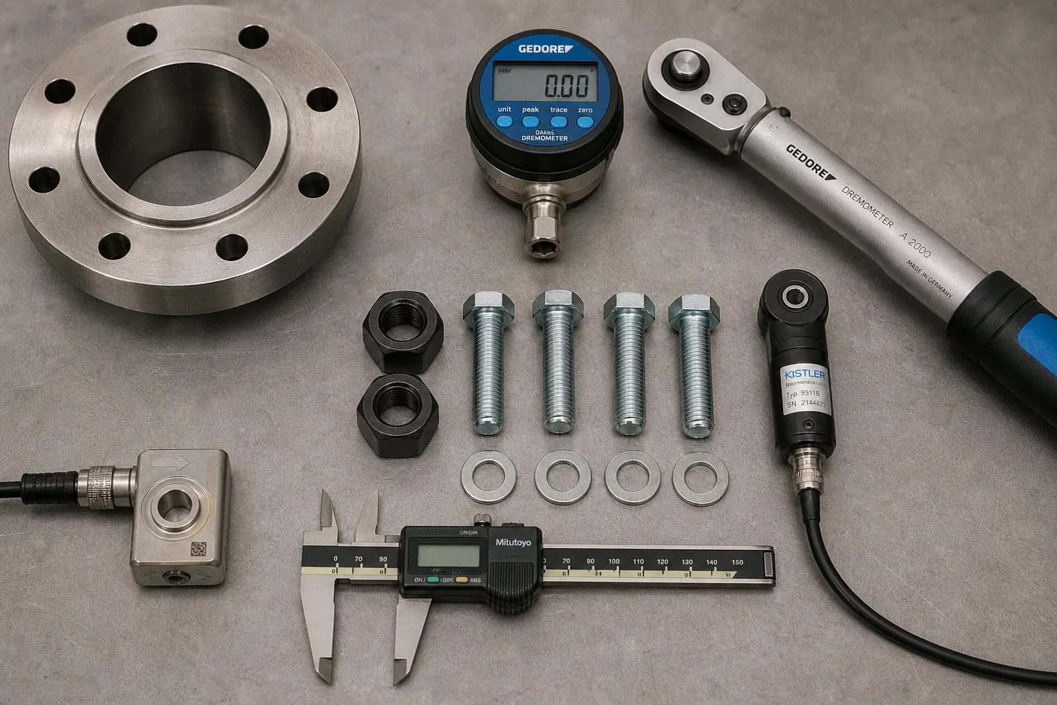
Most industrial fastener failures do not begin with a snapped bolt. They begin earlier, with someone opening a torque chart, spotting an M12 line, and assuming the number on the page will somehow survive a different nut, washer, coating, lubricant, tool, joint stack, and operating temperature.
It will not.
The bolt torque-tension relationship looks seductively simple: nominal preload equals effective torque divided by the nut factor and nominal diameter. In shorthand:
P<sub>pi-nom</sub> = T / (K<sub>nom</sub> × D)
That equation is useful. It is not a permission slip to treat every bolted machine joint like a generic hardware-store assembly. Torque control produces a distribution of preload values, not one clean, obedient clamp force. Friction eats a large share of the input. Change the surface condition and the same wrench setting can deliver a very different result.
I have audited enough equipment documentation to recognise the pattern: a torque value is treated as engineering, while the information needed to justify it lives in scattered drawings, supplier PDFs, tribal knowledge, or nowhere at all. The calculation is rarely the hard part. The data architecture is.
A torque number without its assembly condition is not a specification. It is a rumour with units.
This is the pre-assembly route I would use before calculating preload, selecting a torque, or approving a tightening instruction for a mechanical joint.
Start with the joint function, not the bolt diameter
An industrial fastener preload calculation should start with an uncomfortable question: what must this joint actually prevent?
“Hold the parts together” is not an answer. A bearing housing cap, a gearbox cover, a conveyor frame splice, a motor foot, and a gasketed flange all use threaded fasteners. They do not ask the fasteners to do the same job.
The joint function establishes the preload target logic. Depending on the application, the clamp load may need to:
- prevent joint separation under external tensile loading;
- resist transverse slip between clamped parts;
- preserve bearing-cap geometry and shaft alignment;
- maintain compression on a seal or gasket;
- stop cyclic movement that will fret surfaces and loosen the assembly;
- protect the bolt from excessive alternating load;
- avoid crushing a soft housing, coating, polymer insert, gasket, or thin sheet component.
Do not reverse this sequence. Starting from “we have an M16, grade 8.8” leads directly to the kind of over-engineered arithmetic that produces a very under-engineered joint.
For each joint, I want a one-page definition before anyone reaches for a torque table:
1. Joint purpose and failure mode. State whether the dominant risk is separation, slip, leakage, misalignment, fatigue, loosening, or damage to the clamped components. A preload target for slip resistance can be entirely wrong for a joint carrying a fragile cover.
2. External loading direction and variability. Record axial load, shear load, vibration, thermal cycling, shock, and load reversals. A static mounting bracket and a reciprocating machine frame are not relatives just because both use hex bolts.
3. Clamped-part stack. List every compressed layer in order: housing, shim, washer, bracket, paint layer, gasket, spacer, insert. The stack controls stiffness, embedment, settlement, and how preload redistributes in service.
4. Joint geometry. Capture bolt spacing, edge distances, flange thickness, hole type, thread engagement, bearing-face geometry, and access constraints. A tool that cannot remain square to the fastener is already injecting friction noise before the machine ever starts.
5. Permitted clamped-part compression. This is where many “stronger is better” instincts fail. A high clamp load may distort a bearing seat, crush a gasket, damage a coated surface, or bow a thin cover.
The designation “property class 8.8” or “10.9” tells you something useful about the fastener material properties. It does not establish torque-tension behaviour, corrosion performance, fatigue capability, or a safe preload for your assembled joint. ISO 898-1 is explicit on that point. Treating a property class as a full design file is taxonomy bloat at its finest: one label pretending to contain six missing decisions.
Build the fastener record before calculating anything
A bolt is not “an M10 bolt.” That phrase deletes the variables that decide the result. I would not approve an assembly torque calculation checklist until the fastener record identifies the actual components being installed.
At minimum, capture the following for every unique bolted joint family:
| Parameter | What to record | Why it changes the result |
|---|---|---|
| Fastener type | Bolt, screw, stud, cap screw, threaded rod; head style | Alters the load path, drive interface, and practical tightening method |
| Thread designation | Nominal diameter, pitch, thread standard, length | Diameter enters the torque relationship; pitch and engagement affect behaviour |
| Strength or material grade | Carbon/alloy steel property class, stainless designation, supplier material | Sets mechanical limits but does not independently set assembly torque |
| Nut specification | Grade, style, coating, prevailing-torque feature if present | Nut friction and locking features can dominate torque scatter |
| Washer specification | Material, hardness, diameter, coating, bearing-face form | Changes bearing friction and protects or damages mating surfaces |
| Thread engagement | Engaged length, tapped-hole material, insert details | Controls stripping risk and joint reliability |
| Mating-part materials | Steel, cast iron, aluminium, polymer composite, plated components | Determines compressive limits, galvanic risk, and thermal movement |
| Part condition | New, reused, cleaned, repaired, painted, corroded | “Same bolt” is meaningless if its surface state has changed |
The record needs lot traceability where the joint is safety-critical, high-cycle, pressure-retaining, or expensive to access after commissioning. That is not paperwork theatre. It is the only way to identify whether a later preload issue came from a design decision, a substitution, or a process change nobody thought worth recording.
Do not confuse scope with universality
ISO 16047 provides a framework for torque/clamp-force testing of threaded fasteners and related parts. Its basic scope covers carbon- and alloy-steel metric-thread bolts, screws, studs, and nuts from M3 to M39. That makes it highly relevant to a lot of machinery work.
It does not make it a universal answer for every threaded product thrown into a plant.
The scope excludes, among other things, tension-unloaded set screws, thread-forming screws, and fasteners with added self-locking features. If your joint relies on a prevailing-torque locknut, a special coating, a serrated flange face, or a non-standard thread-forming arrangement, do not quietly smuggle it into a generic torque model. That is how bad categories create bad instructions.
Treat friction as a controlled input, not background noise
The fashionable failure mode in industrial assembly is pretending friction is an annoying detail. It is not a detail. In torque-controlled tightening, it is central to whether the input torque becomes useful clamp load or vanishes into thread and bearing-surface resistance.
The nut factor, often written as K, is a compact way to represent the torque-tension relationship for a specified assembly condition. But it is not a permanent personality trait of a bolt.
I have seen teams enter one K value into a spreadsheet and then reuse it across zinc-flake coated bolts, phosphate-and-oil fasteners, dry stainless hardware, lubricated studs, painted bearing faces, and field-reused nuts. That is not standardisation. It is friction blindness.
The assembly record should state:
- thread condition: dry, oiled, waxed, lubricated, contaminated, cleaned, reused;
- bearing-surface condition under the bolt head or nut;
- lubricant identity, application location, and application quantity;
- bolt, nut, and washer coating or plating system;
- mating-part finish, including paint, anodising, galvanising, or rough machined surfaces;
- visible damage, corrosion, burrs, galling, dents, or embedded debris;
- whether the washer rotates relative to the nut or bolt head during tightening;
- whether the procedure permits reuse of the fastener set.
NASA guidance offers a useful illustration of why generic coefficients are dangerous. In one condition-specific procedure, dry ultrasonically cleaned hardware used K = 0.30, lubricated hardware used K = 0.18, and Arathane-coated threads used K = 0.22. Those were values derived from that organisation’s own testing under defined conditions. They are not a universal industrial menu.
A move from dry to lubricated assembly can radically alter achieved preload at the same torque. So can a change from a clean machined bearing surface to a painted one. If the work instruction says “lightly oil threads as required,” the process is not controlled. It has outsourced clamp-load variation to the judgement of whoever happens to be holding the oil can.
Torque is only a proxy for preload. Friction decides how honest that proxy is.
For corrosion-resistant stainless fasteners, the surface-condition record becomes even more important. Stainless combinations can gall, especially when speed, lubrication, surface finish, and reuse are poorly controlled. “Stainless” is a material family, not a friction coefficient and not a substitute for an assembly procedure.
Match the tightening method to the joint’s risk
A torque wrench is not automatically a preload-control system. It is one method, with known scatter and practical limitations. The method should match the consequence of getting preload wrong.
For routine, low-consequence machine guards or noncritical brackets, controlled torque may be entirely proportionate. For a critical bearing support, a fatigue-sensitive drive connection, a joint with a narrow allowable clamp-load window, or a costly inaccessible assembly, I would ask whether torque-only control is the cheapest thing in the process and the most expensive thing in the field.
The tightening-method record should include the selected method and its actual parameters:
| Method | Useful when | Where it creates friction or risk |
|---|---|---|
| Manual torque wrench | Lower-volume work, accessible fasteners, controlled hardware condition | Operator technique, tool angle, speed, and surface variation add scatter |
| Powered torque tool | Repetitive production assembly | Tool calibration alone does not validate the joint friction condition |
| Torque-plus-angle | Joint has defined seating behaviour and suitable ductility | Requires reliable snug point and stable component geometry |
| Turn-of-nut or angle control | Structural-style joints with validated procedure | Not transferable without joint-specific validation |
| Bolt elongation measurement | Critical studs or accessible long bolts | Needs access, suitable geometry, and trained measurement practice |
| Direct tension indication or load-based methods | High-consequence preload control | Requires compatible hardware and a disciplined installation process |
A tool specification needs more than its brand and maximum torque range. Record:
- calibration status and interval;
- usable accuracy in the target range;
- drive size and extension arrangement;
- crowfoot or offset adaptor geometry;
- tightening speed for powered tools;
- torque direction and reaction-arm placement;
- access angle and whether the tool can stay coaxial;
- seating or snugging step before final tightening;
- final sequence and number of passes;
- cross-pattern, circular, or staged sequence where multiple fasteners share a flange or cap;
- recording method: manual sign-off, tool trace, angle trace, or digital torque trace.
A calibrated tool can still produce an unvalidated assembly. Calibration confirms what the tool applies. It does not prove what preload the joint receives.
For pressure-boundary flanged joints using ring-type gaskets within the bolt-hole circle, ASME PCC-1 provides a relevant discipline around cleaning, inspection, gasket and bolt installation, alignment, manual torque tightening, gaps, bolt length, and load-control selection. Its scope is specific. Do not paste its authority label onto a bearing housing, machine frame, or non-gasketed enclosure and call the problem solved.
Account for temperature, corrosion, and the operating environment
The workshop bench is not the operating environment. Yet too many preload calculations behave as if the joint will remain at room temperature, clean, dry, aligned, and untouched by chemistry. Plants are generous in proving otherwise.
Temperature changes the relationship between the fastener and the clamped parts. If their thermal expansion differs, preload can rise or fall as the assembly heats and cools. A steel bolt clamping aluminium components needs a different level of scrutiny from a steel bolt clamping steel components, particularly where temperature excursions repeat.
Record the full service envelope:
- assembly temperature and expected operating temperature range;
- temperature gradients across the joint, not only the nominal equipment temperature;
- thermal cycling frequency and dwell time;
- ambient humidity, washdown exposure, salt, process vapours, and chemical splash;
- corrosion-protection system on fasteners and mating components;
- electrical isolation or galvanic-corrosion controls where dissimilar metals meet;
- vibration spectrum, impact loading, and cyclic transverse movement;
- access for inspection, retightening, or replacement;
- planned service life and expected maintenance interval.
ISO 3506-1 states unrestricted use of corrosion-resistant stainless-steel fasteners from −20 °C to +150 °C. Outside that range, suitability requires an application-specific assessment of alloy composition, exposure duration, effects on the fasteners and clamped parts, and the corrosive environment. That is a sensible boundary, not a footnote to ignore when the equipment runs hot, cold, or chemically aggressive.
Coatings deserve the same seriousness. A corrosion-resistant coating may improve field life while changing thread friction, bearing friction, or both. That is not an argument against coatings. It is an argument against changing them without revisiting the torque-preload evidence.
Settle the joint before declaring it finished
Embedment and settlement are common sources of preload loss. Paint, rough surfaces, soft washers, burrs, uneven flanges, gasket relaxation, and imperfect seating can all reduce clamp load after the final wrench click.
For joints where settlement matters, the assembly plan should define whether it requires:
1. cleaning and inspection before fit-up;
2. removal of paint or debris from designated bearing surfaces;
3. an initial snugging pass to seat the stack;
4. staged tightening in a prescribed sequence;
5. a dwell period before the final pass;
6. a verification or retightening procedure where the joint design permits it.
Do not write “tighten evenly.” That phrase is procedural fog. Specify the sequence, number of stages, target at each stage if torque control applies, and acceptance condition.
Validate critical joints with the real assembly stack
Here is the line I draw in audits: a generic torque chart may support preliminary planning; it does not replace validation for a critical joint.
SAE J1701:2025 identifies the fastener and mating-part materials, temperature and humidity, finishes, thread and bearing-surface condition, friction, and tightening method as torque-tension variables. For critical joints, it calls for assembly torque values to be established experimentally using the exact assembly components. That is the correct level of discomfort.
“Exact components” means the actual bolt, nut, washer, coating, lubricant, mating material, surface finish, and tool method. Not a cousin from the same catalogue. Not an old qualification report for a different plating supplier. Not a chart published before the team switched from hand tools to pulse tools.
A practical validation plan should define:
- the target preload range and why the joint needs it;
- the test sample definition, including lot and surface condition;
- the representative clamped-part stack or a fixture with equivalent stiffness;
- the tightening method, speed, sequence, and tool;
- how clamp force, bolt elongation, or another preload proxy will be measured;
- the number of samples needed to characterise scatter;
- acceptance limits for preload and installation torque;
- treatment of outliers and observed failure modes;
- the released torque or load-control instruction;
- traceability between validated conditions and production parts.
This is where teams discover whether their design has a broad operating window or a narrow one. If a modest change in lubricant application sends preload from too low to too high, the joint is not robust. Adding more warning text to the work instruction will not fix it. The design, control method, or validation approach needs work.
For high-volume production, I would also define change triggers. A new coating source, new washer design, lubricant substitution, nut redesign, tool change, revised cleaning process, or altered mating-part finish can invalidate the comfortable assumptions buried in the old torque specification.
The pre-assembly release should be short, specific, and hard to misread
The final release package does not need fifty pages of corporate foam. It needs enough structure that a technician, quality engineer, supplier, and field service team all build the same joint.
Before releasing the instruction, I would require these fields to be complete:
- joint ID, drawing revision, and function;
- fastener, nut, washer, and mating-part specifications;
- approved suppliers or controlled alternates where applicable;
- thread, bearing-face, coating, and lubricant condition;
- required cleaning and inspection actions;
- target preload or the validated tightening instruction;
- tightening method, tool, range, calibration requirement, and adaptors;
- tightening sequence, stages, and any dwell or retorque requirement;
- environmental and temperature limits for assembly and service;
- verification method and record requirements;
- explicit change-control triggers;
- engineering owner for deviations.
Anything missing from that list becomes an uncontrolled variable. Calling it “shop-floor flexibility” does not make the preload scatter disappear.
The blunt verdict
I do not start industrial fastener preload calculation steps with a torque chart. I start with the joint, the stack, the surfaces, the tool, and the operating environment. Then I decide whether torque is an acceptable control method and whether the joint needs experimental torque-to-preload validation.
Do this: define the exact assembly condition, validate the critical combinations, and issue a tightening instruction that names every variable that matters.
Not that: copy a diameter-based torque value, lubricate by habit, change coatings midstream, and act surprised when a bolted joint behaves like a random-number generator.