Spherical roller bearings versus tapered roller bearings for heavy radial loads
The friction point usually appears halfway through a shift, not during the design review: a machine is carrying a heavy radial load as intended, but the housing has warmed unevenly, the shaft has…
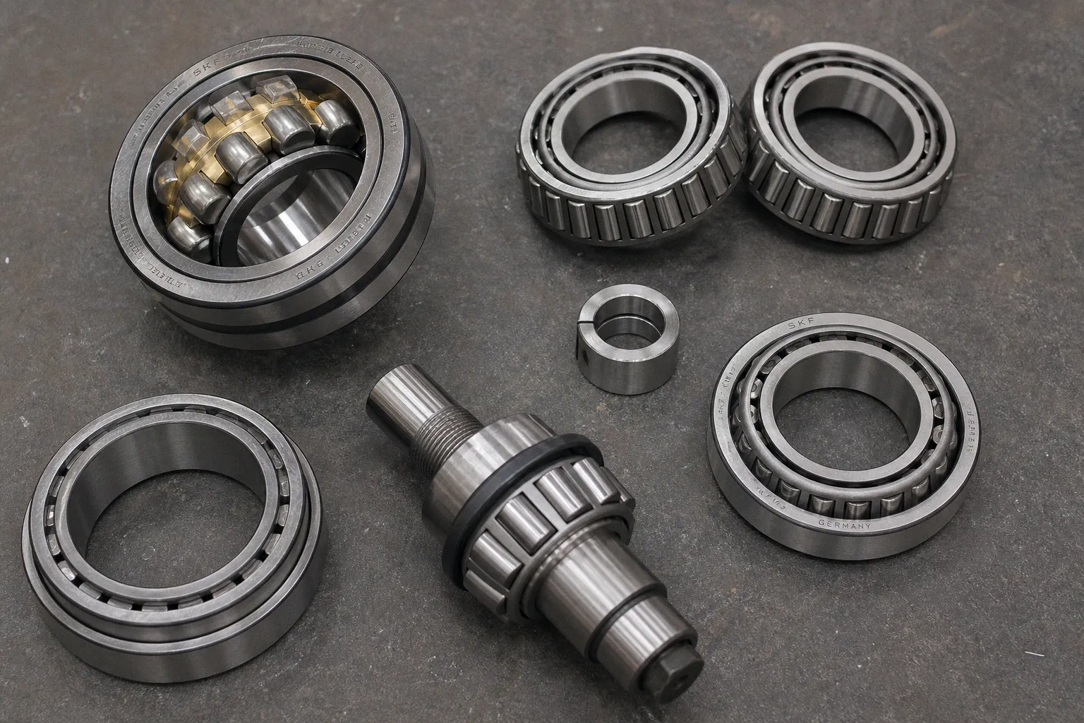
The friction point usually appears halfway through a shift, not during the design review: a machine is carrying a heavy radial load as intended, but the housing has warmed unevenly, the shaft has found its own line by a fraction, and the operator starts hearing a change in the machine’s voice. It may be a rumble near the drive end, a temperature trend that does not settle, or a seal that suddenly has to work much harder than it did when the line was new. On the ground, that is when “high load capacity” stops being a catalog phrase and becomes a question about whether the bearing arrangement is forgiving enough for the machine people actually have to run.
Compare car rental deals in United Kingdom
See available offersPartner link — DiscoverCars comparisonThe comparison between a spherical roller bearing and a tapered roller bearing for heavy radial loads is often framed as a contest with one winner. It is not. A spherical roller bearing can be the calmer, more durable choice where heavy radial force arrives alongside shaft deflection, housing distortion, contamination, and imperfect alignment. A tapered roller bearing can be the more disciplined choice where that radial force comes with a meaningful axial component and the designer needs a defined, stiff location of the shaft.
The right question is not, “Which bearing has the bigger load rating?” It is: what path will radial and axial forces take through this machine, and how much real-world movement can the arrangement tolerate before its carefully calculated performance disappears?
Heavy radial load is only the beginning of the load story
Both bearing types use rollers rather than balls, so both can support serious loads. But their roller geometry changes what they do with the forces arriving at the shaft.
A spherical roller bearing has two rows of barrel-shaped rollers running in a common spherical outer-ring raceway. That geometry allows the inner ring to tilt relative to the outer ring without forcing the rollers into a damaging edge-loaded condition as quickly as a rigid bearing design would. It is built first and foremost to carry high radial load, while also accepting moderate axial load in either direction.
A tapered roller bearing uses conical rollers and raceways. The extended cone surfaces meet at a common point on the bearing axis, creating a natural load path for a combination of radial and axial force. In practice, this makes tapered rollers especially useful when the shaft must resist thrust in a known direction as well as radial load.
The distinction matters because a radial load rarely stays perfectly radial in a working machine. A belt drive pulls in one direction. A helical gear creates thrust. A screw conveyor creates changing axial force as material compacts and releases. A wheel hub sees cornering loads. A gearbox housing flexes under torque. The bearing does not experience a clean diagram from a design spreadsheet; it receives the accumulated result of all these conditions.
| Operating question | Spherical roller bearing | Tapered roller bearing |
|---|---|---|
| Primary strength | High radial load with tolerance for misalignment | Combined heavy radial and axial load |
| Axial-load direction | Moderate axial loads in either direction | Single-row version carries axial load in one direction |
| Response to shaft or housing deflection | Self-aligning geometry accommodates angular misalignment | Requires controlled alignment; misalignment can disrupt contact |
| Typical axial-location role | Often used as a locating or non-locating radial bearing depending on arrangement | Usually mounted in pairs to locate the shaft in both axial directions |
| Setting sensitivity | Radial internal clearance must be managed, especially on tapered bores | Axial setting—endplay, preload, or line-to-line—is fundamental |
| Common heavy-duty environment | Conveyors, crushers, fans, screens, process equipment | Gearboxes, wheel ends, pinions, machine spindles, thrust-loaded shafts |
This is why the phrase spherical roller bearing vs tapered roller bearing load capacity needs some unpacking. There is no defensible universal statement that one always carries more radial load than the other. A compact tapered roller bearing may outperform a spherical bearing of another series in a particular envelope. A large spherical roller bearing may be the obvious radial-load answer in a deflecting conveyor pulley. Bore, outside diameter, width, roller geometry, number of rows, cage design, material, lubrication, speed, mounting fit, and load arrangement all change the result.
A bearing’s catalog rating is not a trophy. It only matters after we understand the load path that reaches the rollers.
If radial load is dominant and the machine structure is expected to move around it, spherical rollers often give us more operating margin. If radial and thrust loads must be carried along a deliberate, stiff path, tapered rollers give us a more purposeful arrangement—but they ask more of the housing, shaft, and assembly process in return.
Misalignment: the condition that separates a stable machine from a fussy one
Misalignment is often treated as a fault to eliminate, and of course we should reduce it wherever we can. But in heavy industrial equipment, some misalignment is not a workmanship error. It is a physical consequence of load, weldment tolerance, thermal growth, foundation settlement, shaft bending, and housing deflection.
A long conveyor pulley shaft can bend under belt tension and material load. A screen housing can move under vibration. A paper machine roll can run hot in a way that changes geometry over the course of production. On the factory floor, the operator does not care whether this movement originated in the shaft, the pedestal, or the frame. They care that the bearing stays cool enough, the machine does not begin to shake, and maintenance does not have to turn every routine inspection into a rescue job.
This is the terrain where spherical roller bearings earn their reputation. Their self-aligning geometry allows the bearing to continue carrying load when the shaft and housing are no longer perfectly coaxial. Manufacturers describe spherical roller bearings as suited not only for high radial loads, but also for difficult conditions that may include marginal lubrication, contamination, critical stresses, and alignment variation. That does not mean they are invulnerable. It means that the bearing has a geometry designed to avoid turning moderate angular error into immediate roller edge stress.
The exact allowable misalignment angle must always come from the catalog for the specific series and operating condition. It changes with load, clearance, bearing size, and surrounding construction. Treating one published angle as a rule for every spherical roller bearing is the kind of shortcut that looks neat in a specification and becomes expensive during commissioning.
Tapered roller bearings demand a more controlled relationship between the shaft, cup, and cone. Their geometry delivers stiffness and excellent combined-load behavior when the assembly is aligned and set correctly. If the housing bore is out of round, the shaft shoulder is not square, or the structure deflects enough to skew the raceways, the contact pattern moves. That can concentrate stress at roller ends and raceway edges, increase heat, and shorten life.
The design decision becomes clearer in an if-then form:
1. If the shaft can bend appreciably under a heavy radial load, and the housing is not a perfectly rigid precision structure, then a spherical roller bearing deserves to be the baseline option.
2. If axial force is substantial, predictable, and central to the machine’s duty, then tapered roller bearings may be the more appropriate architecture, usually in a paired arrangement.
3. If the machine sees both structural movement and meaningful thrust, then we should not force a simple either-or answer. The bearing arrangement, housing stiffness, gear forces, thermal movement, and locating strategy all need to be evaluated together.
4. If alignment quality depends on field assembly rather than controlled factory machining, then the service reality should carry real weight in the selection. A bearing that requires flawless seating but will be installed during a shutdown in a dusty mill is not the same proposition as one installed in a clean build cell.
This is not an argument against tapered rollers. It is an argument against asking a precise bearing arrangement to absorb the consequences of an imprecise machine structure.
Axial location changes the tapered roller conversation
A single-row tapered roller bearing carries axial load in one direction. This is the detail that gets lost when someone sees “combined radial and axial load” in a catalog description and assumes one bearing will locate a shaft both ways. It will not.
For two-direction axial location, single-row tapered roller bearings are generally mounted in pairs. The arrangement can be direct, commonly called an X arrangement, or indirect, commonly called an O arrangement. The names describe how the load lines face each other, but the practical question is how the shaft reacts when force, temperature, and moment loads arrive.
An indirect, or O, arrangement has load lines that spread outward. It is relatively stiff and better suited to accommodating tilting moments than a direct, X arrangement. That makes it a familiar choice where a shaft sees overhung loading or where the support span and moment stiffness matter. The direct arrangement can still be entirely appropriate, but it should be chosen for the actual geometry and force direction rather than because it is the arrangement someone last used successfully.
Spherical roller bearings simplify a different kind of problem. Because they can carry moderate axial load in either direction while tolerating misalignment, they are often comfortable in heavily loaded radial applications where thrust is present but not the dominant design driver. In a typical locating/non-locating bearing concept, one bearing position establishes the shaft axially while the other permits thermal expansion. The exact implementation depends on the bearing type, fit, housing design, and machine layout, but the principle is worth holding onto: shafts grow when they heat, and a system that does not give that growth somewhere safe to go will create load that was never part of the original duty cycle.
Consider a large fan with a belt-driven shaft. If belt pull supplies the dominant radial load, shaft deflection and housing movement are likely part of the real-world context. A spherical roller bearing arrangement may give the fan a better chance of living peacefully with those conditions. If the same shaft also carries a helical gear that applies significant thrust, we need to determine whether the spherical bearing’s axial capability is sufficient or whether a paired tapered arrangement—or a different division of bearing functions—is needed.
The answer comes from the load case, not from brand habit.
Seating and setting: where a good bearing can be damaged before startup
Bearing selection is often discussed as though it ends at the part number. In heavy equipment, the mounting method is part of the bearing design. A correctly selected bearing can still run hot, lose clearance, or fail early if it is seated with the wrong fit or set without regard for operating temperature and load deflection.
For tapered roller bearings, setting is an axial condition between the rollers and raceways. The usual terms are:
- Endplay: a controlled amount of axial internal clearance.
- Preload: a negative-clearance condition in which the rolling elements are deliberately loaded before outside service loads arrive.
- Line-to-line setting: a near-zero condition between endplay and preload.
None of these is automatically “best.” The optimum operating setting depends on the load-induced deflection of the system, thermal expansion, bearing geometry and size, fits, and the materials in the shaft and housing. The assembly setting measured cold is not necessarily the setting the bearing will have when the gearbox reaches operating temperature or when the wheel end takes a long downhill load.
This is where tactile feedback matters, but only as one input. An experienced technician can feel when a component has seated cleanly, when a nut reaches its intended position, or when rotation becomes unexpectedly rough. That knowledge is valuable. It should sit alongside measured endplay, specified torque procedures where applicable, component cleanliness, and verification of the actual arrangement. “It feels about right” is not a setting strategy for a bearing that will carry production through three shifts.
Spherical roller bearings have their own setting discipline, especially when mounted on a tapered bore using a sleeve or by direct drive-up. Advancing the bearing axially on the taper reduces its radial internal clearance. For a 1:12 taper, the approximate radial-clearance reduction is 71 micrometres for each millimetre of axial drive-up. For a 1:30 taper, it is approximately 28 micrometres per millimetre.
Those figures are not an invitation to mount by arithmetic alone. They explain why a little extra movement on the hydraulic nut can have a serious effect at the rollers. We still need the manufacturer’s procedure for the chosen bearing, the original clearance measurement, the mounting method, and the operating condition. Clearance is not a decorative specification; it is the breathing room that allows a heavily loaded bearing to survive thermal changes and elastic deflection.
Preload deserves particular restraint in spherical roller bearing applications. It is not a general-purpose performance upgrade. Excessive preload can generate heat and material fatigue, leading to premature damage unless a specialized lubrication system and a clearly engineered application justify it. In a plant environment, preload that exists only because someone wanted the assembly to “feel tight” is often just hidden friction waiting for the next production run.
The bearing does not know that the assembly was finished on schedule. It only knows its clearance, its lubrication film, and the load it must carry.
Comparing ratings without letting the catalog make the decision for us
Dynamic and static ratings are essential, but they answer different questions.
The basic dynamic load rating supports bearing-life calculations under rolling fatigue. ISO 281 provides methods for calculating basic rating life and modified rating life. Its basic rating life is associated with 90% reliability, while modified life calculations can account for factors such as lubrication condition, contaminated lubricant, and bearing fatigue load.
That last point is especially useful for heavy industrial bearing capacity comparison. Two applications can have the same nominal radial load and the same bearing part number, yet have very different expected outcomes because one has clean, stable lubricant and the other has contamination, intermittent shock, water ingress, or a lubricant film that thins during hot operation. The dynamic rating is not wrong; it is simply not the whole operating story.
Static load rating addresses permanent deformation risk under heavy stationary or slow-moving loads, shock loading, and conditions where the bearing may be heavily loaded without enough rotation to distribute contact stress in the normal way. ISO 76 sets out the method for basic static load rating and static equivalent load. But even this calculation has boundaries. Where normal load distribution is disturbed by misalignment, preload, or unusually large internal clearance, the standard calculation may not fully represent what happens in the bearing, and manufacturer guidance becomes necessary.
When we compare candidate bearings, the sequence should be practical:
1. Build the actual force picture. Separate radial load, axial load, moment load, shock, direction changes, duty cycle, and speed. Do not compress them into one vague “heavy duty” label.
2. Map the bearing arrangement. Identify which bearing locates the shaft, where thermal expansion goes, and how axial load is shared between positions.
3. Check dynamic life using the full operating condition. Include equivalent bearing load, expected speed, lubrication condition, contamination level, and the life target appropriate for the machine’s production role.
4. Check static capacity separately. A bearing can satisfy a fatigue-life calculation and still be poorly suited to startup shock, stalled loads, or a heavy resting load.
5. Review fits, clearance, and temperature. A tight fit may be required to prevent ring creep under load, but it also changes internal clearance. The shaft and housing do not remain dimensionally neutral once the machine is working.
6. Read the selected manufacturer’s application guidance. This is where details on permissible misalignment, mounting drive-up, minimum load, lubrication method, and arrangement-specific limits live.
For spherical roller bearings, a useful operating nuance is speed. A rule of thumb from one major manufacturer is to increase radial clearance when operating speed exceeds 70% of the thermal reference speed. That is not a universal instruction to add clearance whenever a machine looks fast. It is a reminder that temperature changes the bearing’s internal condition, and that the installation clearance must be selected for the heat the machine will actually produce.
For tapered roller bearings, the comparable discipline is to evaluate how operating temperatures alter endplay or preload. If the shaft expands faster than the housing, the bearing setting can tighten. If the housing expands differently, it may loosen. In a compact gearbox, these changes can be decisive. In a field-maintained aggregate plant, they can be made worse by housing damage, spacer variation, or an incorrect cup seating surface.
The selection route that holds up on the factory floor
We can reduce the choice to a workable route without pretending that one bearing type is universally superior.
Choose a spherical roller bearing as the starting point when the application is dominated by heavy radial load and the machine has a credible risk of misalignment, shaft bending, housing flexure, contamination, or difficult service conditions. Think conveyor pulleys, crushing equipment, vibrating machinery, heavy fans, and process rolls. The self-aligning behavior is not a luxury feature; it is a way of protecting the rolling contact from the everyday movement of a loaded machine.
Choose a tapered roller bearing arrangement when radial load arrives with significant axial load and the shaft needs controlled, stiff axial location. Think gear-driven shafts, wheel ends, pinion supports, and arrangements where thrust direction and moment stiffness have been deliberately engineered. The key word is arrangement: a single-row tapered bearing handles axial force in one direction, so paired bearings and their setting are usually the real unit of design.
If the application has heavy radial load, considerable thrust, uncertain alignment, and field assembly constraints all at once, the answer should slow down rather than become more confident. That is the moment to compare specific bearing series and part numbers, study the housing and shaft stiffness, and bring the mounting process into the design review. A bearing choice that looks efficient in a bill of materials can create operator fatigue later through repeated adjustments, elevated noise, seal failures, and unplanned lubrication rounds.
The best bearing arrangement is rarely the one with the most impressive isolated number. It is the one that gives the operator a machine that starts cleanly, reaches a stable temperature, sounds consistent through the shift, and does not turn normal structural movement into a maintenance event. That is what good bearing selection feels like in daily working life: less drama at the housing, less heat at the shaft, and fewer reasons for someone on the floor to stop a line that should have been allowed to run.